Home/
Registry/
Ford/
Bronco/
1978-1979/
1978 Ford Bronco/
Photo
supermotors.net/registry/media/914402
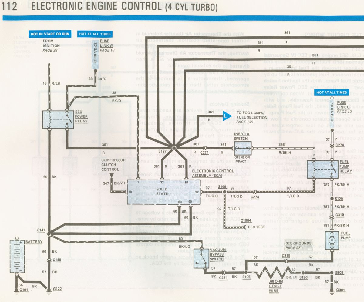
1986 Ford Mustang 2.3L Turbo EEC Wiring Diagram - Fuel Pump Relay & ECA Circuits
Reference · 1978-1979 BroncoAll 116 wiring diagrams
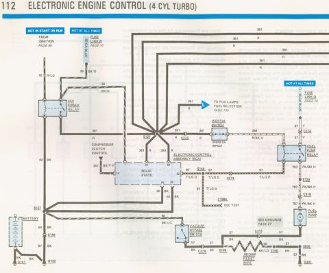
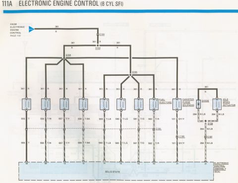
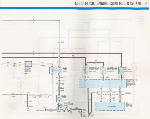
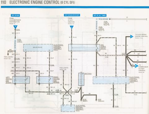
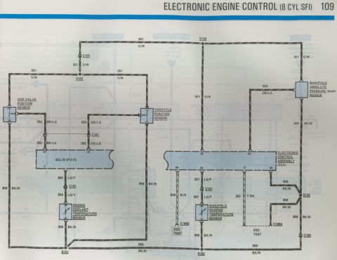

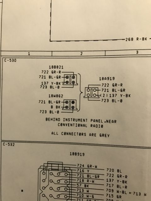
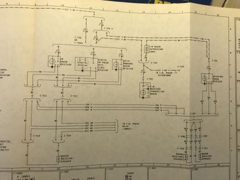
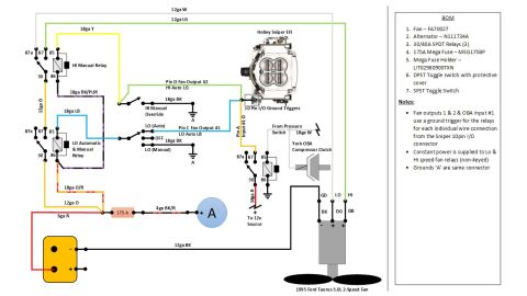


Electronic engine control (4-cyl turbo) wiring schematic showing EEC power relay, ECA solid-state module, fuel pump relay, inertia switch, and EEC test connector grounds.
Part of 1978-1979 Ford Bronco Wiring Diagrams
This is page 112 of a Ford factory wiring diagram book covering the Electronic Engine Control (EEC) system for the 4-cylinder Turbo engine, from a 1986 Ford Mustang manual (per the file set). The schematic shows the EEC power distribution: a HOT IN START OR RUN feed from the ignition switch (circuit 16 R/LG, page 99) and HOT AT ALL TIMES feeds through Fuse Link W (20 GA blue) and Fuse Link Q (18 GA blue) from page 10. It details the EEC Power Relay, circuit 361 (R) power distribution to the Electronic Control Assembly (ECA) pins 1, 37, and 57, the Inertia Switch (opens on impact) feeding circuit 366 R/BK to the Fuel Pump Relay, and circuit 787 PK/BK to the electric Fuel Pump. Ground circuits 57 and 60 (BK) run to grounds G101, G122, and G301, with a Vacuum Bypass Switch and a .68 ohm resist wire in the fuel pump ground path via splices S195/S196. Connectors C274, C149, C319, and the EEC Test connector (C1984, circuit 97 T/LG) are shown, plus cross-references to fog lamps/fuel selection (page 139) and grounds (page 27). Readers can trace wire colors, circuit numbers, splices, and connector locations for diagnosing EEC power and fuel pump circuits.
This document covers 1986, which may differ from this 1978 Ford Bronco.
Is this accurate? Sign in to help verify it.
Frequently asked questions
- What circuit powers the fuel pump on the 4-cylinder turbo EEC system?
- The Fuel Pump Relay supplies circuit 787 (PK/BK H), which runs through splice S129 and connector C319 to the electric Fuel Pump.
- What does the inertia switch do in this diagram?
- The Inertia Switch is in circuit 361/366 ahead of the Fuel Pump Relay and is labeled 'OPENS ON IMPACT', cutting power to the fuel pump relay in a collision.
- Which fuse links feed the EEC system?
- Fuse Link W (20 GA blue) and Fuse Link Q (18 GA blue), both referenced to page 10, provide HOT AT ALL TIMES power; a HOT IN START OR RUN feed comes from the ignition on page 99 via circuit 16 R/LG.
- Where is the EEC test connector shown?
- The EEC TEST connection is at connector C1984, on circuit 97 (T/LG D) branching from splice S149 off ECA pin 22.
- What grounds are used in this circuit?
- Ground circuits 57 and 60 (BK) connect to grounds G101, G122, and G301, with additional ground detail referenced on page 27; a .68 ohm resist wire is in the path near splices S195 and S196.






No comments yet.