Home/
Registry/
Ford/
Bronco/
1978-1979/
1978 Ford Bronco/
Photo
supermotors.net/registry/media/914399
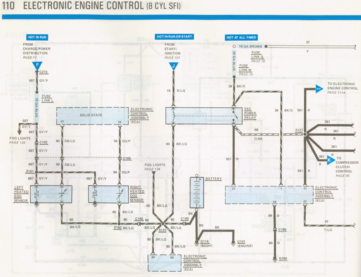
1986 Ford Mustang 5.0 SFI EEC Power & Ground Wiring Diagram - EVTM Page 110
Reference · 1978-1979 BroncoAll 116 wiring diagrams
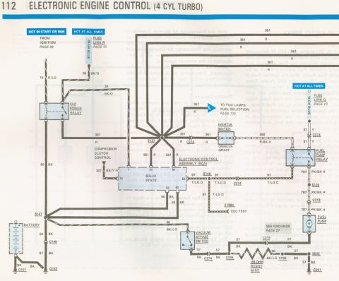
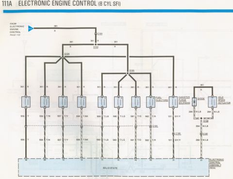
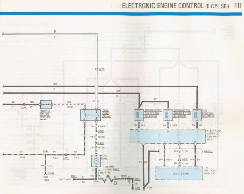
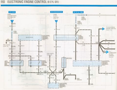
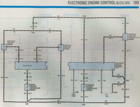
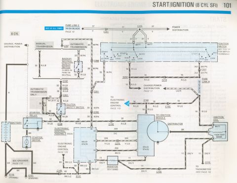
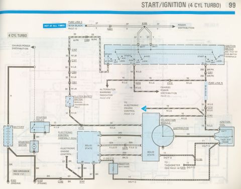



Wiring diagram of electronic engine control for an 8-cylinder SFI, showing the EEC power relay, heated EGO sensors, and compressor clutch control circuits.
Part of 1978-1979 Ford Bronco Wiring Diagrams
This is page 110 of a Ford factory electrical/vacuum troubleshooting manual (EVTM), covering the Electronic Engine Control (EEC) power and ground circuits for the 8-cylinder SFI (Sequential Fuel Injection) engine. The diagram shows three power feeds: a "Hot in Run" circuit from charge/power distribution (page 11) through Fuse Link L on circuit 687 GY/Y feeding the left and right heated EGO (exhaust gas oxygen) sensors; a "Hot in Run or Start" feed from start/ignition (page 101) on circuit 16 R/LG to the EEC power relay coil; and a "Hot at All Times" feed through Fuse Links Q and W (page 10) on circuit 38 BK/O to the EEC power relay. The relay output, circuit 361 R, powers ECA pins 37 and 57 via splice S127, with branches to the compressor clutch control (page 95) and electronic engine control (page 111A). Ground paths run through circuit 60 BK/LG via splices S131 and S160 to grounds G116 (body) and G101 (engine), with ECA grounds at pins 40, 60, 49 (circuit 89 O to G150), and 22 (circuit 97 T/LG). Connectors shown include C210, C192, C166, C149, C190, and cross-references to fog lights (page 134).
This document covers 1986, which may differ from this 1978 Ford Bronco.
Is this accurate? Sign in to help verify it.
Frequently asked questions
- What circuit powers the heated EGO (oxygen) sensors on the 8-cylinder SFI engine?
- Circuit 687 GY/Y, a Hot-in-Run feed from charge/power distribution (page 11) through Fuse Link L (20 GA blue), powers both the left and right heated EGO sensors via connector C192 and splice S161.
- What circuit does the EEC power relay output to the ECA?
- The EEC power relay outputs circuit 361 R, which feeds ECA pins 37 and 57 through splice S127, and also branches to the compressor clutch control (page 95) and electronic engine control (page 111A).
- Where do the ECA ground circuits terminate?
- Circuit 60 BK/LG grounds through splices S131 and S160 to G116 (body ground) and G101 (engine ground). ECA pin 49 grounds through circuit 89 O and connector C190 to G150, and pin 22 uses circuit 97 T/LG.
- What fuse links protect the Hot-at-All-Times feed to the EEC power relay?
- Fuse Link Q (18 GA brown) and Fuse Link W (20 GA blue), both referenced to page 10, protect the Hot-at-All-Times feed on circuit 38 BK/O.
- What powers the EEC power relay coil during cranking and running?
- A Hot-in-Run-or-Start feed from start/ignition (page 101) on circuit 16 R/LG energizes the EEC power relay coil circuit.






No comments yet.