Home/
Registry/
Ford/
Bronco/
1978-1979/
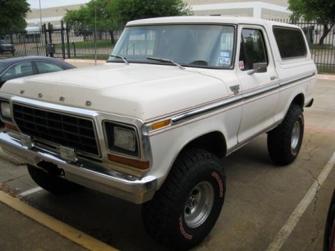
1978 Ford Bronco/
Photo
supermotors.net/registry/media/914401
1986 Ford Mustang 5.0 SFI Wiring Diagram 111A - Fuel Injectors & ECA Pinout
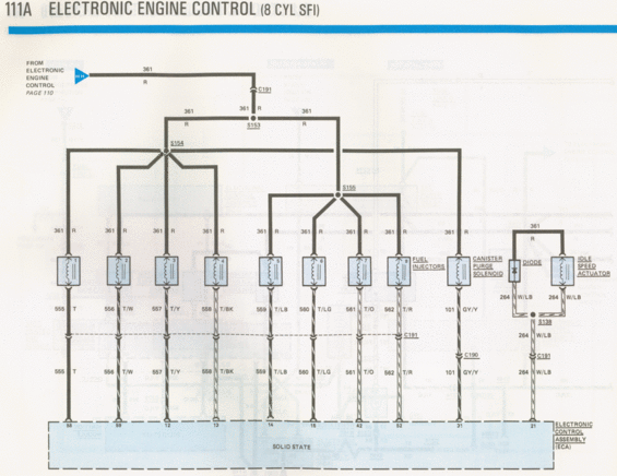
Wiring diagram of electronic engine control for an 8-cylinder SFI, showing the fuel injectors, canister purge solenoid, and idle speed actuator circuits.
This is page 111A of a Ford factory wiring diagram set, covering the Electronic Engine Control system for the 8-cylinder SFI (sequential fuel injection) engine. The diagram shows power distribution from the Electronic Engine Control circuit (continued from page 110 via connector HH) on circuit 361 (red wire), branching through splices S153, S154, and S155 to feed eight fuel injectors, the canister purge solenoid, a diode, and the idle speed actuator. Each fuel injector's return wire is identified by circuit number and color: injector 1 (555 T, ECA pin 58), injector 2 (556 T/W, pin 59), injector 3 (557 T/Y, pin 12), injector 4 (558 T/BK, pin 13), injector 5 (559 T/LB, pin 14), injector 6 (560 T/LG, pin 15), injector 7 (561 T/O, pin 42), and injector 8 (562 T/R, pin 52). The canister purge solenoid returns on circuit 101 GY/Y through connector C190 to ECA pin 31, while the diode and idle speed actuator share circuit 264 W/LB through splice S138 and connector C191 to ECA pin 21. All circuits terminate at the solid-state Electronic Control Assembly (ECA). This page is useful for tracing injector wiring, connector locations (C190/C191), and ECA pinouts on the 5.0L SFI engine.
This document covers 1986, which may differ from this 1978 Ford Bronco.
Is this accurate? Sign in to help verify it.
Frequently asked questions
- What circuit powers the fuel injectors on the 8-cylinder SFI engine?
- Circuit 361 (red wire) feeds all eight fuel injectors, the canister purge solenoid, the diode, and the idle speed actuator via splices S153, S154, and S155.
- What are the wire colors and ECA pins for each fuel injector?
- Injector 1: 555 T, pin 58; Injector 2: 556 T/W, pin 59; Injector 3: 557 T/Y, pin 12; Injector 4: 558 T/BK, pin 13; Injector 5: 559 T/LB, pin 14; Injector 6: 560 T/LG, pin 15; Injector 7: 561 T/O, pin 42; Injector 8: 562 T/R, pin 52.
- Which ECA pin controls the canister purge solenoid?
- The canister purge solenoid is controlled by ECA pin 31 via circuit 101 (GY/Y wire) through connector C190.
- How is the idle speed actuator wired?
- The idle speed actuator is fed by circuit 361 R and returns on circuit 264 W/LB, joining the diode circuit at splice S138, then passing through connector C191 to ECA pin 21.
- Which connectors do the injector wires pass through?
- The injector return circuits (555-562) pass through connector C191 on their way to the Electronic Control Assembly; circuit 101 passes through C190.
Comments
More from this build













No comments yet.