1990 Ford Bronco 5.0L/5.8L Start Ignition Wiring Diagram - TFI Module (20-4)
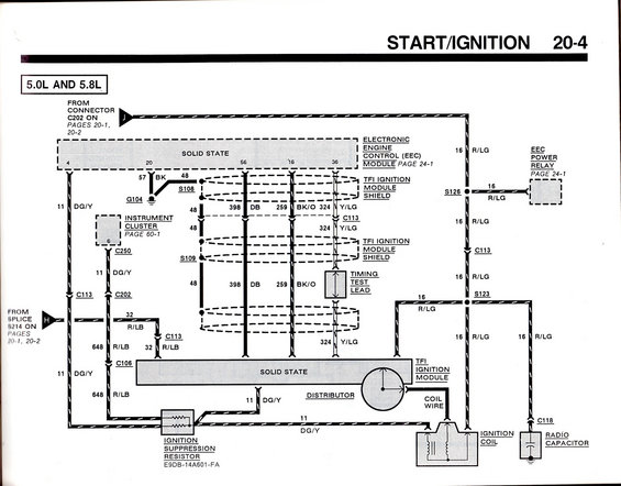
Start/ignition wiring (20-4) for 5.0L/5.8L showing TFI ignition module, ignition coil, distributor, suppression resistor, EEC module and power relay with wire codes R/LG, DG/Y, DB.
This document is page 20-4 of a Ford factory electrical/vacuum troubleshooting manual, covering the Start/Ignition circuit for 5.0L and 5.8L engines. It is a wiring diagram showing the TFI (Thick Film Ignition) ignition module mounted on the distributor, its shielded wiring to the Electronic Engine Control (EEC) module (referenced on page 24-1), the EEC power relay, ignition coil, coil wire, radio capacitor, timing test lead, and ignition suppression resistor (part number E9DB-14A601-FA). Wire circuits are labeled with circuit numbers and color codes: 11 DG/Y (dark green/yellow), 16 R/LG (red/light green), 32 and 648 R/LB (red/light blue), 48, 57 BK (black), 398 DB (dark blue), 259 BK/O (black/orange), and 324 Y/LG (yellow/light green). Connectors shown include C113, C202, C250, C106, and C118; splices include S108, S109, S123, S126, and references to S214; ground G104 is shown at the EEC module shield. Cross-references point to connector C202 and splice S214 on pages 20-1 and 20-2, the instrument cluster on page 60-1, and the EEC module and power relay on page 24-1. This diagram helps diagnose no-start, no-spark, and ignition timing issues on TFI-equipped 5.0L/5.8L trucks.
Is this accurate? Sign in to help verify it.
Frequently asked questions
- What engines does this start/ignition wiring diagram cover?
- The diagram is labeled for the 5.0L and 5.8L engines.
- What wire color feeds the ignition coil and TFI ignition module power?
- Circuit 16 R/LG (red/light green) feeds the ignition coil, TFI ignition module, radio capacitor, and EEC power relay through splices S126 and S123 and connector C113.
- What is the part number of the ignition suppression resistor?
- E9DB-14A601-FA, shown feeding circuit 11 DG/Y to the TFI ignition module/distributor.
- Which circuits connect the TFI ignition module to the EEC module?
- Shielded circuits 48, 398 DB, 259 BK/O, and 324 Y/LG run between the TFI ignition module and the EEC module, with 324 Y/LG also going to a timing test lead.
- Where is the EEC power relay documented?
- The diagram references the EEC power relay and the EEC module on page 24-1, the instrument cluster on page 60-1, and connector C202/splice S214 on pages 20-1 and 20-2.
Comments
More from this build













No comments yet.