1990 Ford Bronco Instrument Cluster Wiring Diagram 60-2 (Gas, No Tachometer)
Reference · 1987-1991 BroncoAll 175 wiring diagrams
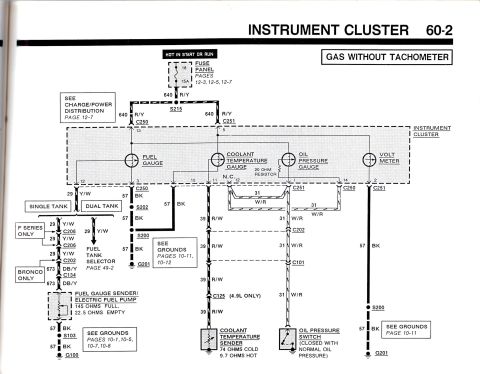
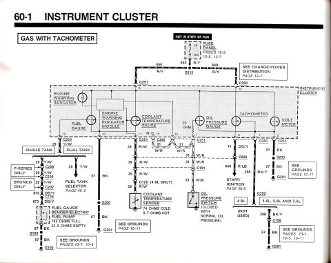












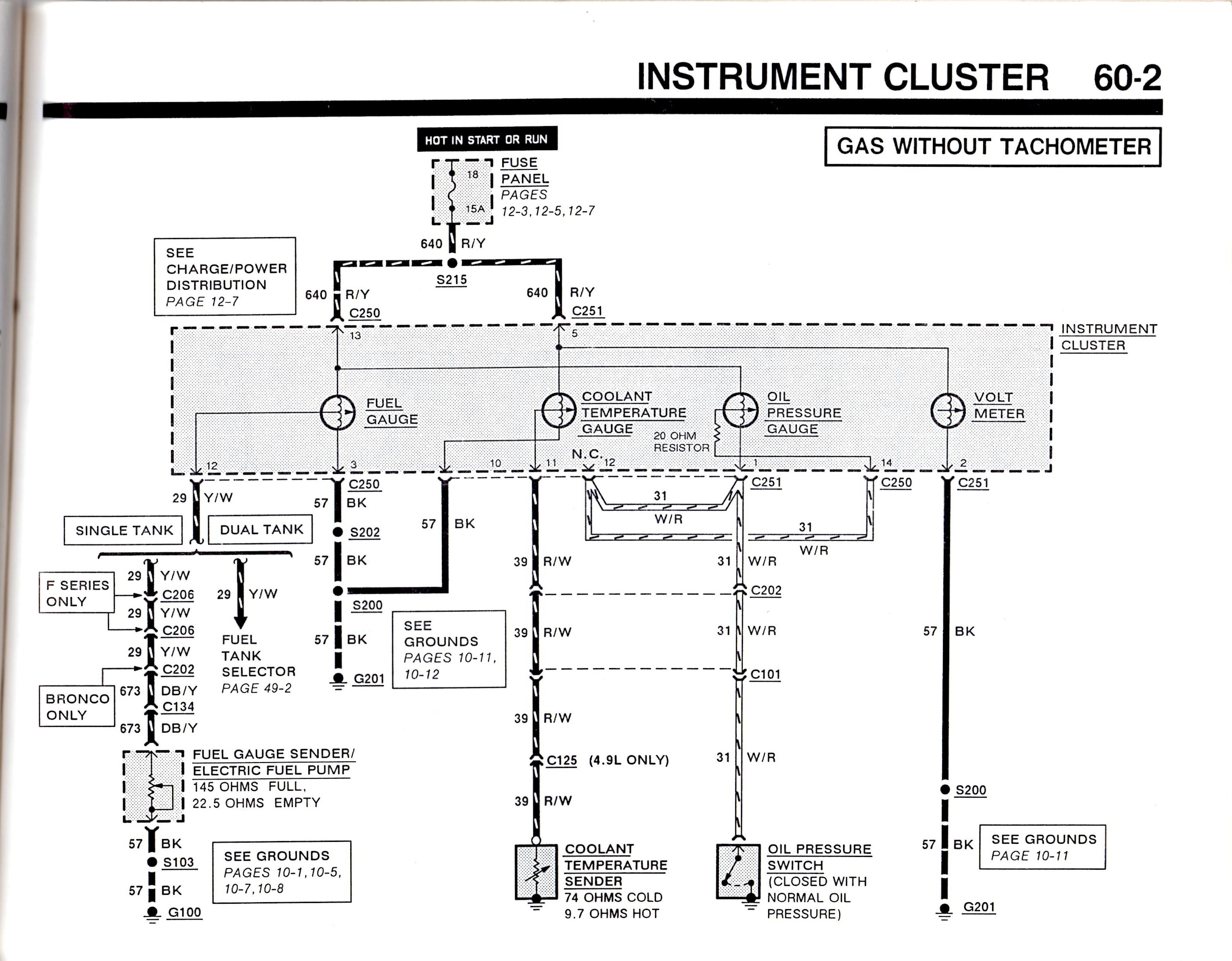
Instrument cluster wiring (60-2, gas without tach) showing fuel, coolant temp, oil pressure gauges and voltmeter fed by fuse 18 via 640 R/Y; lists fuel sender 145 ohms full / 22.5 ohms empty.
Part of 1987-1991 Ford Bronco Wiring Diagrams
This document is page 60-2 of a Ford electrical/vacuum troubleshooting manual, showing the instrument cluster wiring diagram for gas engine vehicles without a tachometer. Power comes from fuse 18 (15A) in the fuse panel, hot in Start or Run, feeding circuit 640 R/Y through splice S215 into cluster connectors C250 (pin 13) and C251 (pin 5). The diagram covers four gauges: fuel gauge, coolant temperature gauge, oil pressure gauge (with an internal 20 ohm resistor), and volt meter. The fuel gauge circuit (29 Y/W) shows single-tank and dual-tank variants, with F-Series-only and Bronco-only branches (Bronco uses circuit 673 DB/Y through C134) leading to the fuel gauge sender/electric fuel pump, rated 145 ohms full and 22.5 ohms empty. The coolant temperature circuit (39 R/W) runs through C202, C101, and C125 (4.9L only) to the sender, rated 74 ohms cold and 9.7 ohms hot. The oil pressure circuit (31 W/R) leads to the oil pressure switch, closed with normal oil pressure. Grounds use circuit 57 BK through splices S103, S200, S202 to grounds G100 and G201, with cross-references to grounds pages 10-1 through 10-12, charge/power distribution page 12-7, and fuel tank selector page 49-2.
Is this accurate? Sign in to help verify it.
Frequently asked questions
- What fuse powers the instrument cluster gauges in this diagram?
- Fuse 18, a 15A fuse in the fuse panel, hot in Start or Run, feeding circuit 640 (R/Y) through splice S215 to cluster connectors C250 and C251.
- What are the fuel gauge sender resistance values?
- The fuel gauge sender/electric fuel pump reads 145 ohms when full and 22.5 ohms when empty.
- What resistance should the coolant temperature sender show?
- 74 ohms cold and 9.7 ohms hot, on circuit 39 (R/W).
- What wire circuit does the Bronco fuel gauge use to the sender?
- On Bronco only, the fuel gauge wire changes from 29 Y/W at C202 to circuit 673 DB/Y through connector C134 to the fuel gauge sender/electric fuel pump.
- How does the oil pressure gauge circuit work?
- The oil pressure gauge includes a 20 ohm resistor and connects via circuit 31 (W/R) through C202 and C101 to the oil pressure switch, which is closed with normal oil pressure.






No comments yet.