5-Pin Automotive Relay Pinout Diagram: Terminals 30, 85, 86, 87, 87a

Reference · 1987-1991 BroncoAll 111 schematics
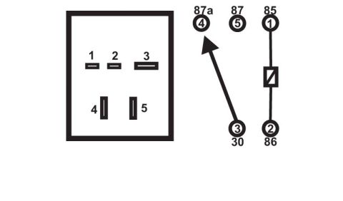
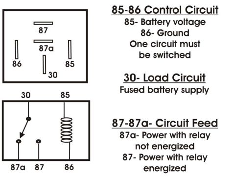
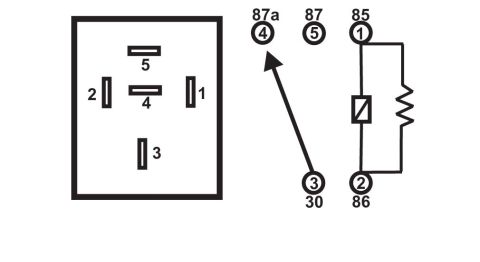









Relay diagram showing the 5-pin socket layout and internal coil and contact schematic with terminal numbers 30, 85, 86, 87 and 87a.
Part of 1987-1991 Ford Bronco Schematics
This document is an unlabeled schematic illustration of a common 5-pin automotive relay, uploaded to a 1990 Ford Bronco gallery. The left half shows the physical relay base with the blade terminal layout: terminal 5 at top (horizontal blade), terminal 4 in the center (horizontal blade), terminal 2 on the left, terminal 1 on the right, and terminal 3 at the bottom. The right half shows the internal electrical schematic and maps each physical pin number to its standard relay terminal designation: pin 4 = 87a, pin 5 = 87, pin 1 = 85, pin 3 = 30, and pin 2 = 86. The schematic depicts the switched contact arm resting from terminal 30 (pin 3) toward terminal 87a (pin 4), indicating the normally-closed contact, while the coil element between terminals 85 (pin 1) and 86 (pin 2) is drawn with a resistor in parallel across it. A reader can use this diagram to identify which physical blade on the relay corresponds to which circuit function (power input 30, normally-open output 87, normally-closed output 87a, and coil terminals 85/86) when testing, wiring, or replacing a relay. The document contains no year, make, model, or part number text.
Is this accurate? Sign in to help verify it.
Frequently asked questions
- Which pin number corresponds to relay terminal 30?
- Pin 3 corresponds to terminal 30, shown at the bottom of the relay base layout.
- Which terminals are the relay coil connected to?
- The coil (with a resistor drawn in parallel) is connected between pin 1 (terminal 85) and pin 2 (terminal 86).
- Which terminal is 87a and where is it located?
- Terminal 87a is pin 4, the horizontal blade in the center of the relay base. The switch arm from terminal 30 rests toward it in the schematic.
- Where is terminal 87 on this relay?
- Terminal 87 is pin 5, the horizontal blade at the top of the relay base layout.






No comments yet.