Ford EEC-IV TPS Pinpoint Test DH Schematic - TP Sensor Connector Pinout
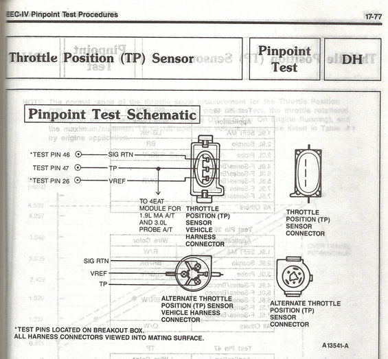
Ford EEC-IV pinpoint test schematic (17-77) for the Throttle Position (TP) sensor: test pins 26 VREF, 46 SIG RTN, 47 TP at breakout box, with standard and alternate TP connector views for 1.9L MA A/T and 3.0L.
This page (17-77) is from a Ford EEC-IV Pinpoint Test Procedures manual, covering Pinpoint Test DH for the Throttle Position (TP) Sensor. It presents the "Pinpoint Test Schematic" showing how the TP sensor circuit connects to breakout box test pins: Test Pin 46 for SIG RTN (signal return), Test Pin 47 for TP (throttle position signal), and Test Pin 26 for VREF (reference voltage). A branch from the TP signal wire is noted as going "to 4EAT module for 1.9L MA A/T and 3.0L Probe A/T" applications. The diagram illustrates both the standard TP sensor vehicle harness connector and TP sensor connector (oval 3-pin style), as well as an alternate TP sensor vehicle harness connector and alternate TP sensor connector (round style) with the same three circuits: SIG RTN, VREF, and TP. Footnotes state that the asterisked test pins are located on the breakout box and that all harness connectors are viewed into the mating surface. The figure reference number is A13541-A. Faint mirrored bleed-through from the reverse page shows an application/wire-color table listing engines such as the 4.9L, 5.0L, 5.8L, and 7.5L F-Series/Bronco.
Is this accurate? Sign in to help verify it.
Frequently asked questions
- What breakout box test pins are used for the Ford EEC-IV TP sensor pinpoint test?
- Test Pin 46 for SIG RTN, Test Pin 47 for TP, and Test Pin 26 for VREF. The asterisked test pins (46 and 26) are located on the breakout box.
- What are the three circuits on the Ford TP sensor connector?
- SIG RTN (signal return), TP (throttle position signal), and VREF (reference voltage).
- Which applications have the TP signal also routed to the 4EAT module?
- The schematic notes the TP signal goes to the 4EAT module for the 1.9L MA automatic transmission and the 3.0L Probe automatic transmission.
- How are the harness connectors depicted in this schematic?
- All harness connectors are viewed into the mating surface, per the footnote. The page shows both a standard TP sensor connector and an alternate (round) TP sensor connector style.
- What pinpoint test is this page from?
- It is Pinpoint Test DH (Throttle Position Sensor) from the EEC-IV Pinpoint Test Procedures, page 17-77, figure A13541-A.
Comments
More from this build














No comments yet.