Ford Bronco Explorer Auto-Dim Mirror Wiring Diagram - OHC Plug & Wire Colors
Reference · 1992-1996 BroncoAll 411 wiring diagrams
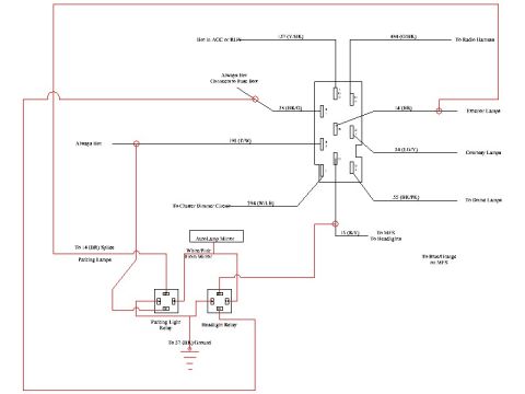
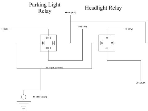
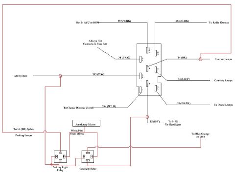
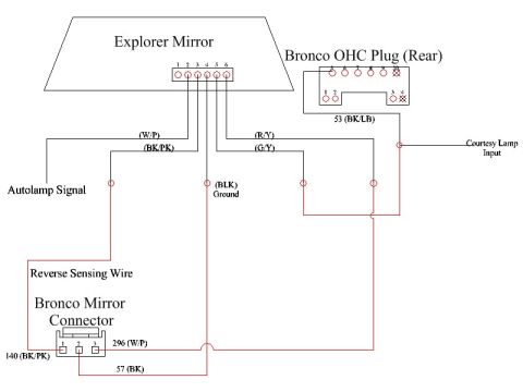
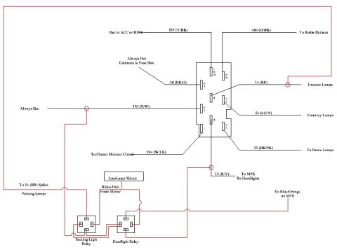














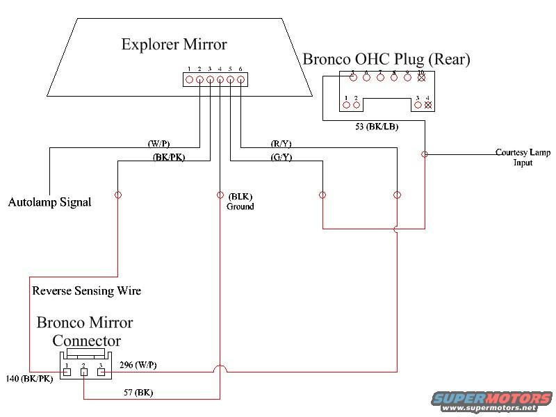
Wiring diagram mapping an Explorer mirror to a Bronco mirror connector with color-coded autolamp, ground and reverse-sensing wires.
Part of 1992-1996 Ford Bronco Wiring Diagrams
This is a hand-drawn wiring diagram showing how to connect a Ford Explorer auto-dimming/autolamp mirror into a Ford Bronco, using the Bronco's rear overhead console (OHC) plug and the Bronco mirror connector. The Explorer mirror uses a 6-pin connector; its wires are identified by color: (W/P) white/pink, (BK/PK) black/pink, (R/Y) red/yellow, (G/Y) green/yellow, and (BLK) black ground. The Bronco OHC (Rear) plug is drawn with its pin layout, and circuit 53 (BK/LB, black/light blue) is identified there, tied to a "Courtesy Lamp Input." The Bronco mirror connector is shown as a 3-pin plug with Ford circuit numbers: 296 (W/P) on pin 2, 140 (BK/PK) on pin 1, and 57 (BK) ground on pin 3. Callouts identify the Autolamp Signal wire and the Reverse Sensing Wire. Red lines indicate the interconnections between the Explorer mirror pins, the OHC plug, and the Bronco mirror connector. A reader can learn which Explorer mirror wires correspond to which Bronco factory circuits (296 power, 140 autolamp/reverse sense, 57 ground, 53 courtesy lamp) when retrofitting an Explorer auto-dim mirror with autolamp and reverse-sensing features into a Bronco.
Is this accurate? Sign in to help verify it.
Frequently asked questions
- What wire colors does the Explorer mirror connector use?
- The 6-pin Explorer mirror connector wires shown are (W/P) white/pink, (BK/PK) black/pink, (R/Y) red/yellow, (G/Y) green/yellow, and (BLK) black for ground.
- What circuits are on the Bronco mirror connector?
- The 3-pin Bronco mirror connector carries circuit 296 (W/P) on pin 2, circuit 140 (BK/PK) on pin 1, and circuit 57 (BK) on pin 3.
- Which wire at the Bronco OHC rear plug is the courtesy lamp input?
- Circuit 53 (BK/LB, black/light blue) at the Bronco OHC (Rear) plug is tied to the Courtesy Lamp Input.
- Which wires carry the Autolamp Signal and Reverse Sensing functions?
- The diagram labels an Autolamp Signal line coming from the Explorer mirror's (W/P)/(BK/PK) side, and a Reverse Sensing Wire routed down to the Bronco Mirror Connector area.
- What is the ground wire in this mirror wiring setup?
- The Explorer mirror has a (BLK) black Ground wire, and the Bronco mirror connector ground is circuit 57 (BK).
- How many pins are on each connector shown?
- The Explorer mirror connector has 6 pins, the Bronco mirror connector has 3 pins, and the Bronco OHC rear plug is drawn with a multi-pin layout (an upper row of about 10 pins and a lower row with pins 1, 2, 3, 4).






No comments yet.