1994 Ford Bronco Anti-Theft System Wiring Diagram - Disarm Switches & Fuse 19
Reference · 1992-1996 BroncoAll 411 wiring diagrams
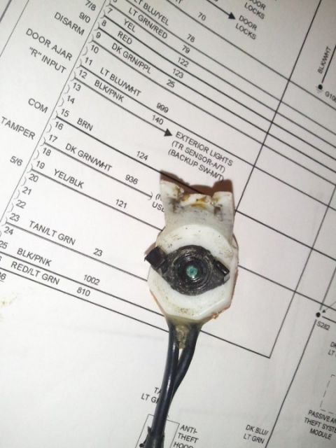
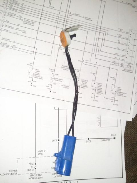
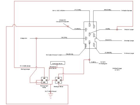
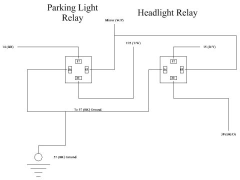
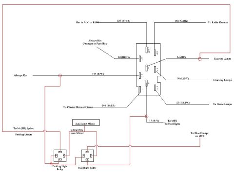














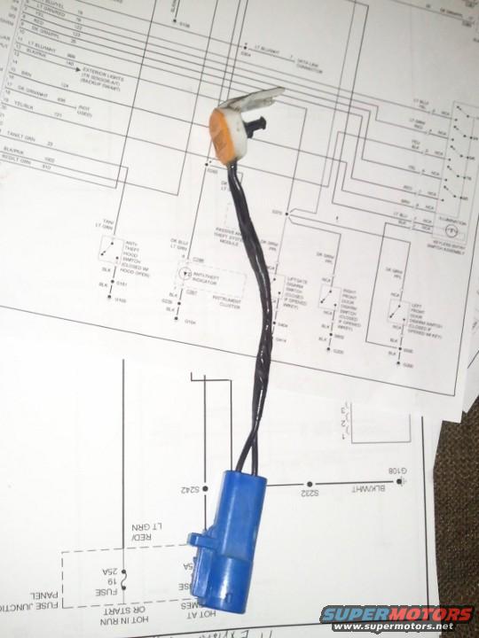
Wiring diagram showing color-coded circuits and fuse junction panel connections with a connector laid over the page.
Part of 1992-1996 Ford Bronco Wiring Diagrams
This image is a photograph of a small two-wire electrical switch or sensor with a blue connector body placed on top of printed automotive wiring diagram pages. The visible upper diagram appears to cover a passive anti-theft system circuit, showing components such as a Passive Anti-Theft System Module, anti-theft hood switch (closed with hood open), anti-theft indicator in the instrument cluster, liftgate disarm switch, right and left front door disarm switches (closed if opened with key), a keyless entry switch assembly with illumination, and a data link connector. Wire colors legible include LT BLU/WHT, DK GRN/WHT, BLK/PNK, YEL/BLK, TAN/LT GRN, RED/LT GRN, DK BLU/LT GRN, and DK GRN/PPL, with grounds G101, G104, and G108 and connectors C286/C287 noted. The lower diagram shows fuse junction panel feeds labeled 'HOT IN RUN OR START' and 'HOT AT ALL TIMES,' including Fuse 19 (25A), splices S242 and S232, and a BLK/WHT ground path to G108. Much of the text is obscured by the physical part and the camera angle, so the transcription is partial. The photo was filed with a 1994 Ford Bronco, though the diagrams themselves show no explicit year, make, or model.
Is this accurate? Sign in to help verify it.
Frequently asked questions
- What anti-theft components are shown in this wiring diagram?
- The visible portions show a Passive Anti-Theft System Module, an anti-theft hood switch (closed with hood open), an anti-theft indicator in the instrument cluster, a liftgate disarm switch, and left and right front door disarm switches (closed if opened with key), plus a keyless entry switch assembly.
- What fuse and amp rating are visible on the power distribution page?
- Fuse 19, rated 25A, in the fuse junction panel, fed from circuits labeled 'HOT IN RUN OR START' and 'HOT AT ALL TIMES.' A second fuse with a partially visible 5A rating is also shown.
- What wire colors are identified in the diagram?
- Legible wire colors include LT BLU/WHT, DK GRN/WHT, BLK/PNK, YEL/BLK, TAN/LT GRN, RED/LT GRN, DK BLU/LT GRN, DK GRN/PPL, and BLK/WHT.
- What ground and splice points are called out?
- Grounds G101, G104, and G108 are visible, along with splices S242 and S232; the BLK/WHT wire from S232 runs to ground G108.
- When do the door disarm switches close according to the diagram?
- The left and right front door disarm switches and the liftgate disarm switch are labeled as closed if opened with the key; the hood switch is closed with the hood open.






No comments yet.