1994 Ford Bronco A/C & Heater Blower Wiring Diagram - Fuse 1/6, Clutch Circuit
Reference · 1992-1996 BroncoAll 411 wiring diagrams
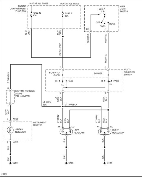
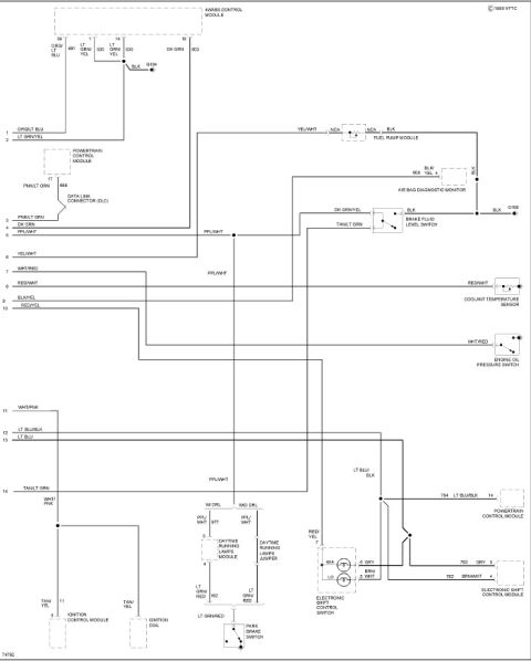
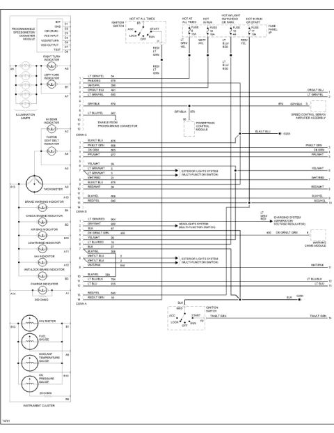
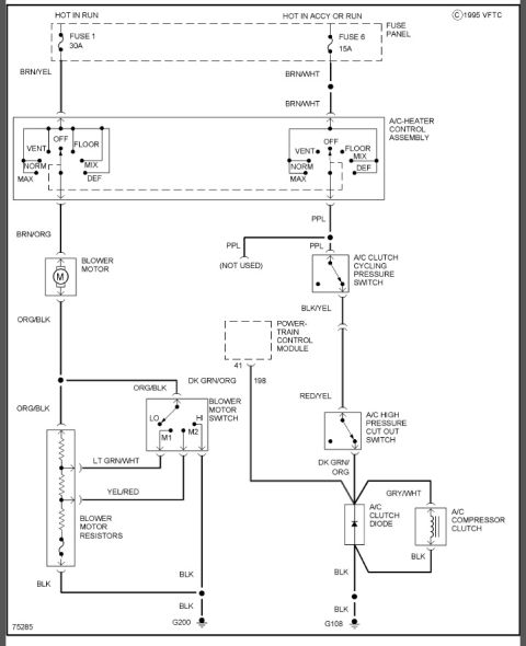
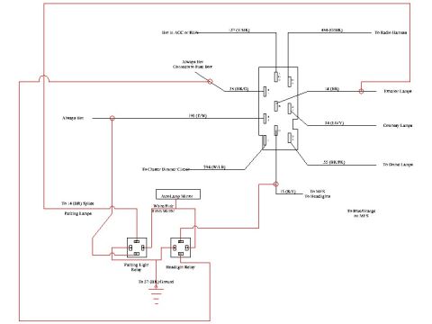














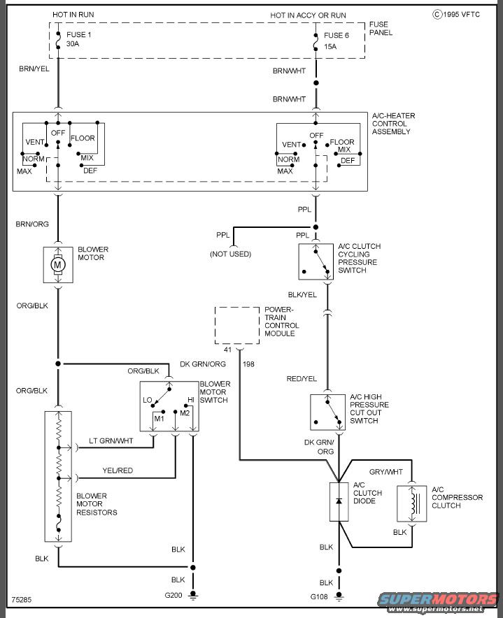
1995 VFTC A/C-heater wiring: 30A fuse 1 and 15A fuse 6, A/C-heater control assembly, blower motor and resistors, cycling/high-pressure switches, A/C clutch diode and compressor clutch, ground G200.
Part of 1992-1996 Ford Bronco Wiring Diagrams
This document is a single-page automotive wiring diagram (copyright 1995 VFTC, drawing number 75285) covering the A/C and heater blower circuit. Power comes from two fuse panel sources: Fuse 1 (30A, hot in RUN) feeding the blower side on a BRN/YEL wire, and Fuse 6 (15A, hot in ACCY or RUN) feeding the compressor clutch side on a BRN/WHT wire. Both feeds pass through the A/C-Heater Control Assembly, whose mode selector positions (OFF, VENT, FLOOR, NORM, MIX, MAX, DEF) are shown. The blower branch runs BRN/ORG to the blower motor, then ORG/BLK to the blower motor switch (LO, M1, M2, HI) and blower motor resistors, with LT GRN/WHT, YEL/RED, and DK GRN/ORG speed wires, grounding at G200 through BLK wires. The A/C branch runs PPL from the control assembly through the A/C clutch cycling pressure switch, then BLK/YEL to the powertrain control module (pin 41, circuit 198), RED/YEL to the A/C high pressure cut out switch, and DK GRN/ORG to the A/C clutch diode and A/C compressor clutch (GRY/WHT), grounding at G108. The diagram gives complete wire colors, switch positions, fuse ratings, and ground locations for diagnosing blower or A/C compressor clutch problems.
Is this accurate? Sign in to help verify it.
Frequently asked questions
- What fuse powers the blower motor circuit in this diagram?
- Fuse 1, a 30A fuse in the fuse panel that is hot in RUN, feeding the A/C-heater control assembly on a BRN/YEL wire.
- What fuse powers the A/C compressor clutch circuit?
- Fuse 6, a 15A fuse hot in ACCY or RUN, feeding the control assembly on a BRN/WHT wire.
- What switches are in line with the A/C compressor clutch?
- The A/C clutch cycling pressure switch (PPL in, BLK/YEL out) and the A/C high pressure cut out switch (RED/YEL in, DK GRN/ORG out), with the powertrain control module connected at pin 41 on circuit 198.
- What wire color feeds the blower motor?
- BRN/ORG from the A/C-heater control assembly feeds the blower motor; the motor's return side is ORG/BLK to the blower motor switch and resistors.
- Where do the circuits ground?
- The blower motor switch/resistor side grounds through BLK wires at G200, and the A/C clutch diode/compressor clutch side grounds through BLK wires at G108.






No comments yet.