1992-96 Ford Bronco Instrument Cluster Wiring Diagram (Sheet 2 of 2) - Senders

Reference · 1992-1996 BroncoAll 411 wiring diagrams
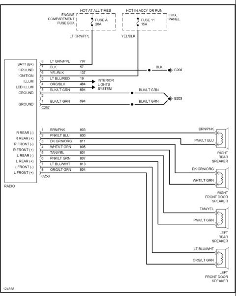
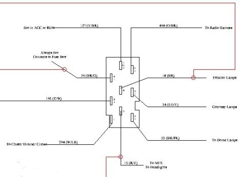
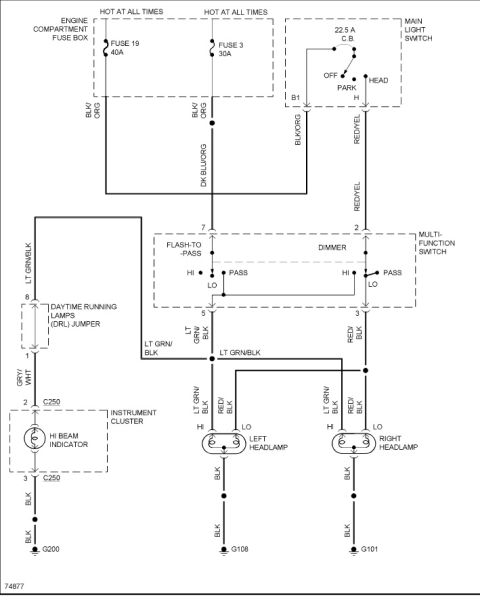
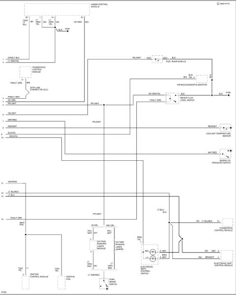
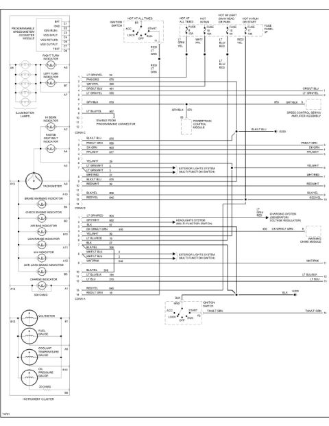
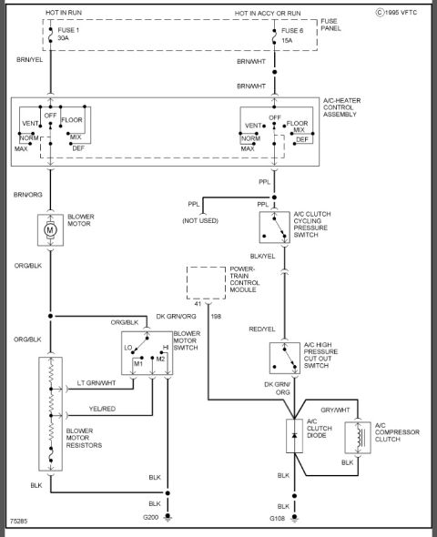
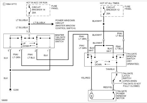
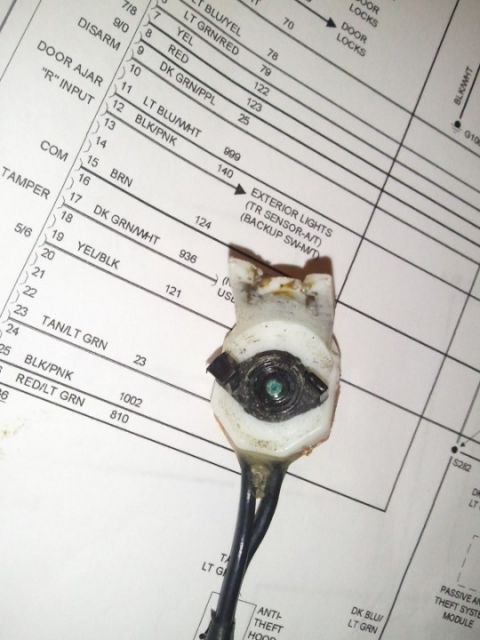














Wiring diagram showing engine, fuel pump, sensor and module circuits with color-coded wires and connectors.
Part of 1992-1996 Ford Bronco Wiring Diagrams
This is sheet 2 of 2 of an instrument cluster wiring diagram (© 1995 VFTC, drawing 74792) uploaded for a 1992-96 Ford Bronco. It shows the sender and module connections that feed the instrument cluster, whose continuation points (numbered 1-14 with wire colors) appear along the left edge and link back to sheet 1. Components shown include the 4WABS Control Module (pins 39, 1, 14, 18 with circuits 491, 530, 603 and a black ground to G104), the Powertrain Control Module (pin 17, circuit 658 PNK/LT GRN to the Data Link Connector), the Fuel Pump Module (YEL/WHT), the Air Bag Diagnostic Monitor (circuit 608 BLK/YEL, ground G108), the Brake Fluid Level Switch (DK GRN/YEL, TAN/LT GRN, BLK), the Coolant Temperature Sensor (RED/WHT), and the Engine Oil Pressure Switch (WHT/RED). It also details the Daytime Running Lamps Module (PPL/WHT circuit 977, LT GRN/RED circuit 162) versus the DRL jumper for vehicles without DRL, the Park Brake Switch, the Electronic Shift Control Switch (4X4/LO indicators) and Electronic Shift Control Module (circuits 782 BRN/WHT, 783 GRY, 784 LT BLU/BLK), plus the Ignition Control Module and Ignition Coil (TAN/YEL tach signal). Grounds G104 and G108 are identified.
Is this accurate? Sign in to help verify it.
Frequently asked questions
- What wire color carries the fuel level/pump signal from the fuel pump module?
- The fuel pump module connects via a YEL/WHT wire; the module's other pins are marked NCA and its ground is BLK.
- What circuit and color connect the Air Bag Diagnostic Monitor to the cluster?
- Circuit 608, a BLK/YEL wire at pin 4 of the Air Bag Diagnostic Monitor, with a BLK ground going to G108.
- Which wires run to the Electronic Shift Control Module?
- Circuit 783 GRY (pin 5), circuit 782 BRN/WHT (pin 4), and circuit 784 LT BLU/BLK (pin 14 of the Powertrain Control Module); the shift control switch 4X4 and LO indicators use pins 8 (GRY) and 5 (WHT/BRN-WHT) with RED/YEL on pin 7.
- What is the wire color for the coolant temperature sensor and the oil pressure switch?
- The coolant temperature sensor uses a RED/WHT wire and the engine oil pressure switch uses a WHT/RED wire.
- How does the Daytime Running Lamps circuit differ with and without DRL?
- With DRL, a Daytime Running Lamps Module is used (pin 5 PPL/WHT circuit 977, pin 4 LT GRN/RED circuit 162 to the park brake switch); without DRL, a Daytime Running Lamps Jumper connects PPL/WHT to LT GRN/RED directly.






No comments yet.