1992-96 Ford Bronco Instrument Cluster Wiring Diagram - Connector Pinouts 1 of 2
Reference · 1992-1996 BroncoAll 411 wiring diagrams
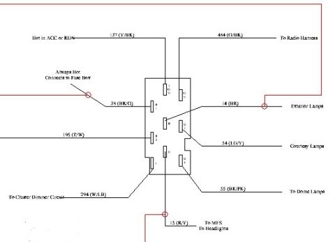
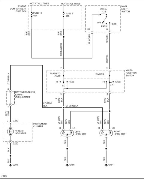
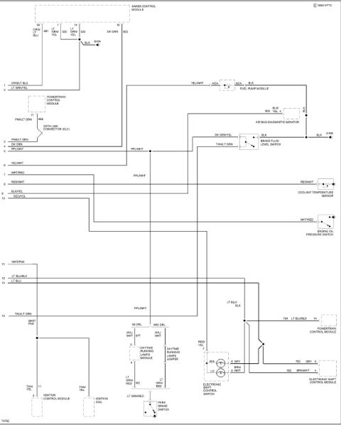
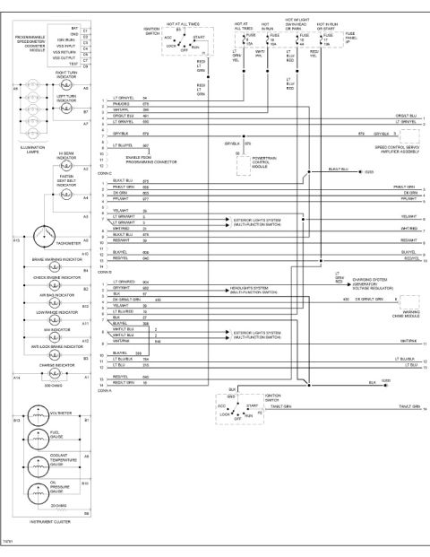














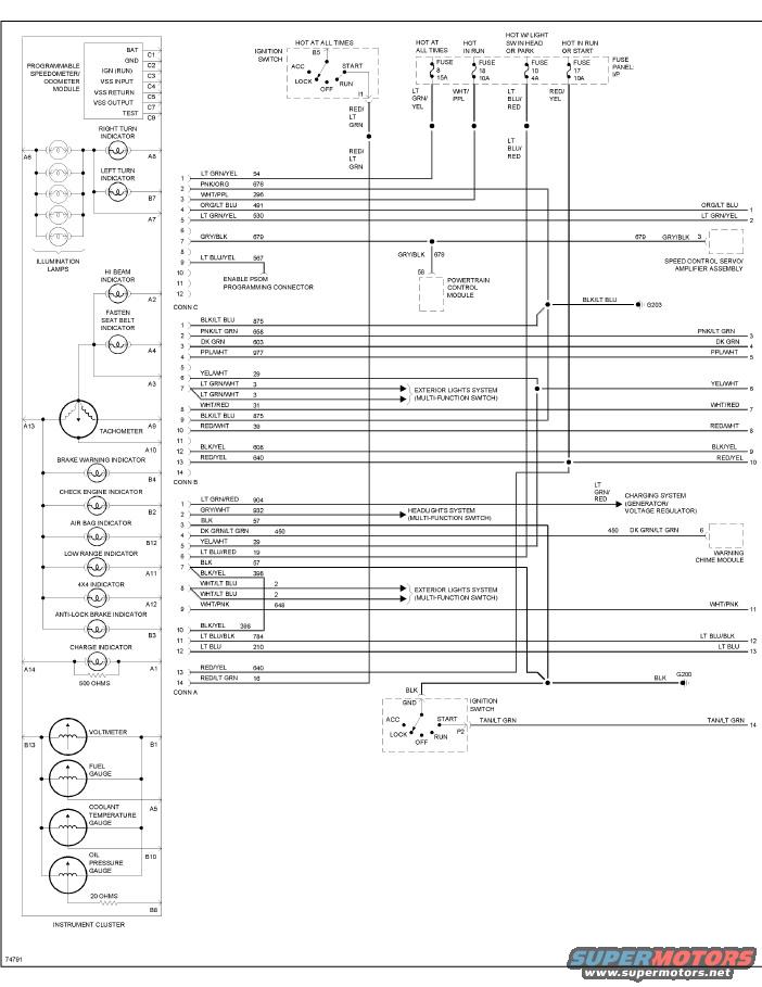
Wiring diagram for the instrument cluster showing gauges, indicators, connectors and color-coded circuits.
Part of 1992-1996 Ford Bronco Wiring Diagrams
This document is a wiring diagram for the instrument cluster of a 1992-96 Ford Bronco (uploaded as page 1 of 2 of a cluster diagram set for a 1994 Bronco). The left side shows the instrument cluster internals: programmable speedometer/odometer module (PSOM) with pins C1-C8 (BAT, GND, IGN RUN, VSS input/return/output, TEST), turn indicators, illumination lamps, hi-beam, fasten seat belt, tachometer, brake warning, check engine, air bag, low range, 4x4, anti-lock brake, and charge indicators, plus voltmeter, fuel, coolant temperature, and oil pressure gauges with cluster pin identifiers (A1-A14, B1-B13). The right side details three cluster connectors (Conn A, B, C) with pin numbers, wire colors, and circuit numbers (e.g., LT GRN/YEL 54, GRY/BLK 679, BLK/LT BLU 875, DK GRN/LT GRN 450). Power feeds are shown from fuses 8 (15A), 18 (10A), 10 (4A), and 17 (10A) in the instrument panel fuse panel, plus the ignition switch. Interconnections are shown to the powertrain control module, speed control servo/amplifier, exterior lights and headlights systems via the multi-function switch, warning chime module, charging system (generator/voltage regulator), the PSOM programming connector, and grounds G200 and G203. Diagram reference number 74791 appears at bottom left.
Is this accurate? Sign in to help verify it.
Frequently asked questions
- What fuses power the Bronco instrument cluster in this diagram?
- Four fuses in the I/P fuse panel are shown: Fuse 8 (15A, hot at all times), Fuse 18 (10A, hot in run), Fuse 10 (4A, hot with light switch in head or park), and Fuse 17 (10A, hot in run or start), plus feeds through the ignition switch.
- What are the PSOM (programmable speedometer/odometer module) pin functions?
- C1 BAT, C2 GND, C3 IGN (RUN), C4 VSS INPUT, C5 VSS RETURN, C7 VSS OUTPUT, and C8 TEST.
- What wire connects the cluster to the speed control servo/amplifier and PCM?
- The GRY/BLK circuit 679 wire runs from connector C pin 6 to the speed control servo/amplifier assembly and branches at splice 58 to the powertrain control module.
- Where does the instrument cluster ground?
- BLK/LT BLU wire 875 grounds at G203, and a BLK wire through the ignition switch grounds at G200.
- Which wire enables PSOM programming?
- The LT BLU/YEL circuit 987 wire on connector C pin 8 goes to the ENABLE PSOM programming connector.






No comments yet.