1994 Ford Bronco Headlight Wiring Diagram - Fuses, Dimmer Switch & Wire Colors

Reference · 1992-1996 BroncoAll 411 wiring diagrams
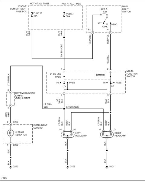
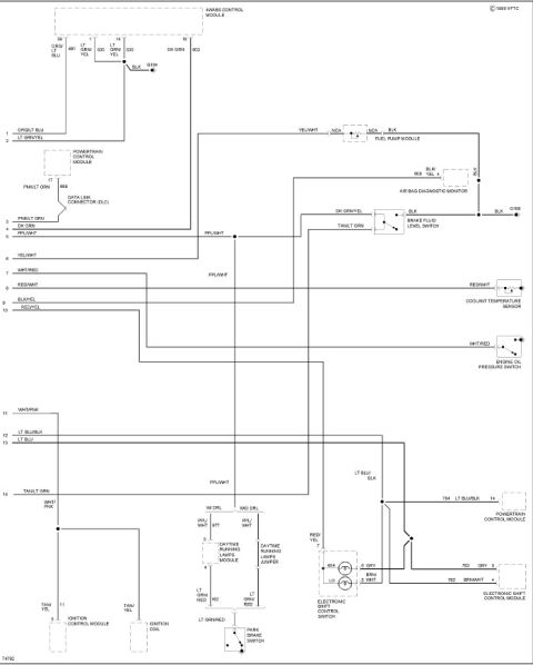
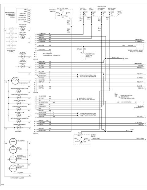














Wiring diagram of the headlamp circuit including main light switch, fuses, daytime running lamps, and color-coded wiring.
Part of 1992-1996 Ford Bronco Wiring Diagrams
This document is a headlight circuit wiring diagram (diagram number 74877) uploaded for a 1994 Ford Bronco. It shows power originating from two hot-at-all-times sources in the engine compartment fuse box: Fuse 19 (40A) and Fuse 3 (30A), both leaving on BLK/ORG wires. Fuse 19 feeds the main light switch, which contains a 22.5 A circuit breaker and OFF/PARK/HEAD positions; terminal B1 receives BLK/ORG and terminal H outputs RED/YEL. Fuse 3 feeds the multi-function switch pin 7 on a DK BLU/ORG wire for the flash-to-pass function, while RED/YEL feeds pin 2 for the dimmer (HI/LO/PASS) function. Switch outputs are LT GRN/BLK (pin 5, high beam) and RED/BLK (pin 3, low beam). The LT GRN/BLK high-beam circuit also passes through a daytime running lamps (DRL) jumper (pins 8 to 1, exiting as GRY/WHT) to the high-beam indicator in the instrument cluster via connector C250, grounding at G200. Both left and right headlamps receive LT GRN/BLK (HI) and RED/BLK (LO) feeds and ground on BLK wires at G108 (left) and G101 (right). The diagram documents wire colors, fuse ratings, connector pins, and ground locations for headlight troubleshooting.
Is this accurate? Sign in to help verify it.
Frequently asked questions
- What fuses power the headlight circuit in this diagram?
- Fuse 19 (40A) and Fuse 3 (30A) in the engine compartment fuse box, both hot at all times, with BLK/ORG output wires. The main light switch also contains a 22.5 A circuit breaker.
- What wire colors are used for the high and low beams?
- High beam is LT GRN/BLK (multi-function switch pin 5) and low beam is RED/BLK (pin 3). Both left and right headlamps receive these colors at their HI and LO terminals.
- Where do the headlamps ground?
- The left headlamp grounds on a BLK wire at G108, the right headlamp at G101, and the high-beam indicator circuit grounds at G200.
- How does the flash-to-pass feature get power?
- Fuse 3 (30A) feeds the multi-function switch pin 7 via a DK BLU/ORG wire, powering the flash-to-pass function even with the main light switch off.
- What is the DRL jumper shown in the diagram?
- A daytime running lamps (DRL) jumper between pins 8 and 1; it receives LT GRN/BLK and outputs GRY/WHT to the high-beam indicator in the instrument cluster through connector C250.






No comments yet.