Holley vs 80555 Carburetor Throttle Linkage Lever Geometry Comparison Diagram

Reference · 1980-1986 BroncoAll 34 schematics
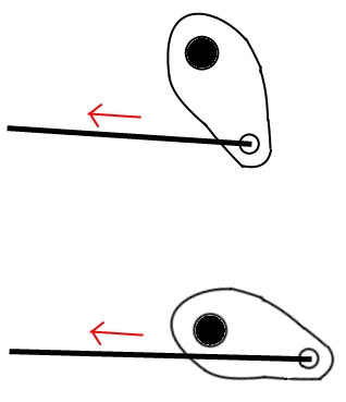




Mechanical schematic illustrating a pivoting cam lever and cable in two positions with direction-of-travel arrows.
Part of 1980-1986 Ford Bronco Schematics
This document is a text-free, hand-drawn schematic comparing two throttle-linkage lever geometries, apparently contrasting a standard Holley carburetor throttle arm with that of a Holley 80555 (per the upload filename 'Holley vs 80555.jpg'). Each of the two drawings shows a teardrop-shaped lever with a central pivot hole (drawn as a large solid black circle) and a small attachment hole at its tip where a long linkage rod connects. A red arrow indicates the direction the rod pulls (to the left) in both cases. The key difference illustrated is the lever's orientation relative to the rod: in the top drawing the lever hangs mostly vertically with the rod attaching at its lower tip, while in the bottom drawing the lever lies mostly horizontally with the rod attaching at its far right tip. This changes the effective lever arm and geometry of the throttle linkage. Because the drawing contains no text, all applicability information (vehicle, carburetor model, year) comes solely from the uploader's filename and gallery attribution to a 1981 Ford Bronco. A reader can learn the relative geometry difference between the two linkage setups but no specific measurements or part identifications from the image itself.
Is this accurate? Sign in to help verify it.
Frequently asked questions
- What does this diagram show?
- Two hand-drawn schematics of a throttle lever and linkage rod, each with a red arrow showing the rod being pulled to the left. The two drawings differ in the orientation of the lever relative to the rod.
- What is the difference between the two drawings?
- In the top drawing the lever is oriented mostly vertically with the rod attached at its lower tip; in the bottom drawing the lever lies mostly horizontally with the rod attached at its far right tip, changing the linkage geometry.
- Are there any part numbers or measurements in the diagram?
- No. The image contains no text, labels, dimensions, or part numbers, only the two lever/rod sketches and red directional arrows.
- What do the red arrows indicate?
- They point to the left along each rod, indicating the direction of rod movement or pull in both linkage configurations.
No comments yet.