Intake Manifold Heat Strip Wiring Diagram - Temp Switch & Cab Switch Circuit
Reference · 1980-1986 BroncoAll 92 wiring diagrams
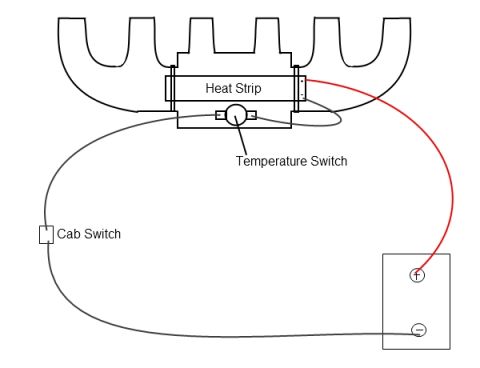






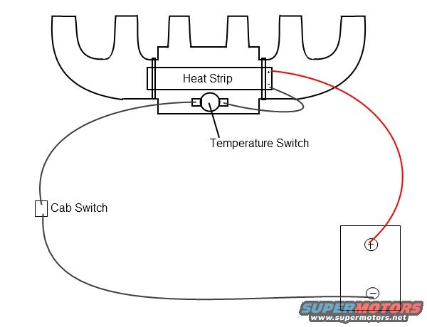
Wiring diagram showing an intake heat-strip circuit with temperature switch, cab switch and color-coded battery leads.
Part of 1980-1986 Ford Bronco Wiring Diagrams
This is a simple, hand-drawn wiring diagram for an intake manifold heat strip (intake heater) circuit, uploaded to a 1981 Ford Bronco gallery under the filename "Intake heat.jpg." The diagram shows four components: an intake manifold (drawn in outline at the top), a "Heat Strip" element mounted under the manifold runners, a "Temperature Switch" attached to the heat strip assembly, and a "Cab Switch." A battery is drawn at the lower right with (+) and (−) terminals. The circuit path is straightforward: a red wire connects the battery's positive terminal directly to one side of the heat strip; the other side of the circuit runs from the temperature switch, through the cab-mounted switch, and back to the battery's negative terminal. From this document a reader can learn the basic wiring scheme for adding or troubleshooting an intake heat strip: power is fed constantly from the battery positive, while the ground/return side is controlled in series by both a temperature switch (presumably to cut the heater when warm) and a manually operated switch in the cab. No wire gauges, part numbers, fuse ratings, relay, or year/model applicability information is given anywhere in the diagram.
Is this accurate? Sign in to help verify it.
Frequently asked questions
- What components are shown in this intake heat strip wiring diagram?
- Four labeled elements: a Heat Strip mounted under the intake manifold, a Temperature Switch on the heat strip assembly, a Cab Switch, and a battery with (+) and (−) terminals.
- How is the heat strip wired to the battery?
- A red wire runs from the battery's positive (+) terminal directly to the heat strip. The return side goes from the temperature switch, through the cab switch, and back to the battery's negative (−) terminal.
- Are the temperature switch and cab switch wired in series or parallel?
- In series, the wire from the temperature switch passes through the cab switch before returning to the battery negative terminal, so both must be closed for the heat strip to operate.
- Does the diagram specify wire gauges, fuses, or a relay?
- No. The diagram only shows wire routing (a red positive feed and a gray return wire); no fuses, relay, wire gauge, or amperage information is included.






No comments yet.