Home/
Registry/
Ford/
Bronco/
1980-1986/
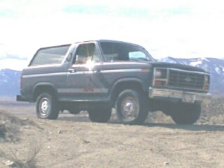
“That dirty old truck”/
Photo
supermotors.net/registry/media/1169342
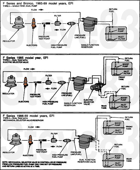
1985-89 Ford F-Series & Bronco EFI Fuel System Diagrams - Single & Dual Tank

Reference · 1980-1986 BroncoAll 34 schematics
'85-89 Fuel Systems
IF THE IMAGE IS TOO SMALL, click it.
For Type 2 SFR, read this page & the NEXT several:

For Type 4 DFR, read this page & the NEXT several:

See also:

Part of 1980-1986 Ford Bronco Schematics
This document is a set of three Ford fuel system schematics covering EFI (electronic fuel injection) configurations on F-Series trucks and Broncos from 1985 through 1989. The top diagram, labeled Type 2, Single Tank, Dual Pump (F-Series and Bronco, 1985-89), shows fuel flow from the in-tank boost pump and inlet filter through a single function reservoir, high pressure fuel pump, inline filter, pressure test point, injectors, and pressure regulator, with a return fuel line back to the tank. The middle diagram, Type 3, Dual Tank with Electric Selector Valve (F-Series, 1985 only), adds front and rear tanks each with a boost pump and inlet filter, joined by an electric selector valve feeding a single function reservoir. The bottom diagram, Type 4, Dual Tank with Mechanical Selector Valve/Reservoir (F-Series, 1986-89), replaces the electric valve with a dual function reservoir/valve; a note explains that the mechanical selector valve is controlled by pressure from the low pressure fuel pump and that only one set of pressure and return lines is active at a time. A reader can learn the component layout, flow direction, and pressure/return line routing for each EFI fuel system type, including the location of the pressure test point.
This document covers 1985-1989, which may differ from this 1983 Ford Bronco.
Is this accurate? Sign in to help verify it.
Frequently asked questions
- What fuel system does a 1985-89 Ford Bronco with EFI use?
- Per the diagram, the F-Series and Bronco 1985-89 EFI setup is Type 2, Single Tank, Dual Pump: an in-tank boost pump with inlet filter feeds a single function reservoir, then a high pressure fuel pump, filter, injectors, and regulator, with a return fuel line back to the tank.
- How do dual-tank EFI F-Series trucks switch between tanks?
- In 1985 (Type 3), an electric selector valve switches between front and rear tanks before the single function reservoir. In 1986-89 (Type 4), a dual function reservoir/valve with a mechanical selector valve is used, controlled by pressure from the low pressure fuel pump; only one set of pressure and return lines is active at a time.
- Where is the fuel pressure test point in these Ford EFI systems?
- In all three diagrams, the pressure test point is on the fuel line between the inline filter and the injectors, downstream of the high pressure fuel pump.
- How many fuel pumps do these EFI systems have?
- Two per active tank: a low-pressure boost pump inside each tank (with an inlet filter) and a frame-mounted high pressure fuel pump fed by the reservoir.
- What is the difference between the 1985 and 1986-89 dual-tank systems?
- The 1985 Type 3 system uses a single function reservoir with a separate electric selector valve, while the 1986-89 Type 4 system uses a combined dual function reservoir/valve with a pressure-operated mechanical selector valve.


No comments yet.