Home/
Registry/
Ford/
Bronco/
1992-1996/
“Eddie Bauer”/
Photo
supermotors.net/registry/media/1000237
Ford Bronco Premium Sound Radio Wiring Diagram - Amplifier & Speaker Pinout
Reference · 1992-1996 BroncoAll 411 wiring diagrams
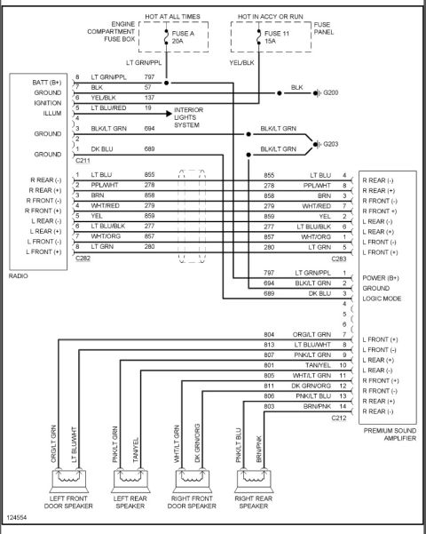
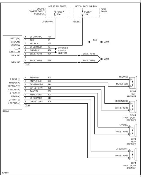














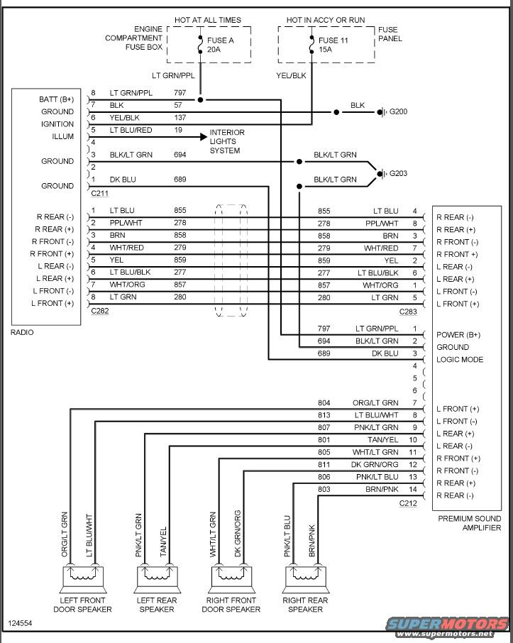
Factory radio-with-premium-sound wiring diagram: connectors C211/C262/C283/C212, power on fuse A 20A and fuse 11 15A, amplifier feeds and color-coded speaker circuits.
Part of 1992-1996 Ford Bronco Wiring Diagrams
This wiring diagram shows the radio circuit with premium sound amplifier for a Ford Bronco (uploaded as a 1996 Bronco premium radio circuit). Power feeds come from Fuse A (20A) in the engine compartment fuse box, hot at all times, on a LT GRN/PPL wire (circuit 797), and from Fuse 11 (15A) in the fuse panel, hot in ACCY or RUN, on a YEL/BLK wire (circuit 137). The radio connects through connector C211 with battery, ground (grounds G200 and G203), ignition, and illumination (LT BLU/RED, circuit 19, to the interior lights system). Speaker-level outputs pass from radio connector C282 to amplifier input connector C283, pin-for-pin with wire colors and circuit numbers (277-280, 855-859) for all four left/right front/rear channels. The premium sound amplifier (connector C212, 14 pins) receives power (797), ground (694), and a logic mode signal (689, DK BLU), and drives four speakers: left front door (ORG/LT GRN, LT BLU/WHT), left rear (PNK/LT GRN, TAN/YEL), right front door (WHT/LT GRN, DK GRN/ORG), and right rear (PNK/LT BLU, BRN/PNK), circuits 801-813. Useful for radio replacement, amplifier bypass, or speaker wiring diagnosis, since every pin, wire color, and circuit number is labeled.
Is this accurate? Sign in to help verify it.
Frequently asked questions
- What fuses power the radio in this diagram?
- Fuse A, a 20A fuse in the engine compartment fuse box (hot at all times, LT GRN/PPL wire, circuit 797) and Fuse 11, a 15A fuse in the fuse panel (hot in ACCY or RUN, YEL/BLK wire, circuit 137).
- What are the speaker wire colors at the premium sound amplifier?
- Left front (+) ORG/LT GRN 804, left front (-) LT BLU/WHT 813, left rear (+) PNK/LT GRN 807, left rear (-) TAN/YEL 801, right front (+) WHT/LT GRN 805, right front (-) DK GRN/ORG 811, right rear (+) PNK/LT BLU 806, right rear (-) BRN/PNK 803.
- Which wire is the amplifier logic mode signal?
- The DK BLU wire, circuit 689, on pin 3 of amplifier connector C212, which also connects to radio pin 1 of connector C211.
- Where does the radio get its illumination signal?
- Pin 5 of connector C211, LT BLU/RED wire, circuit 19, which connects to the interior lights system.
- What connectors are used in this radio circuit?
- C211 (radio power/ground/ignition/illumination), C282 (radio speaker output) mating to C283 (amplifier input), and C212 (premium sound amplifier). Grounds are at G200 and G203.






No comments yet.