Home/
Registry/
Ford/
Bronco/
1992-1996/
“Eddie Bauer”/
Photo
supermotors.net/registry/media/1007161
2001 Ford F-150 Heated Seat Wiring Diagram - Modules, Switches & Fuses
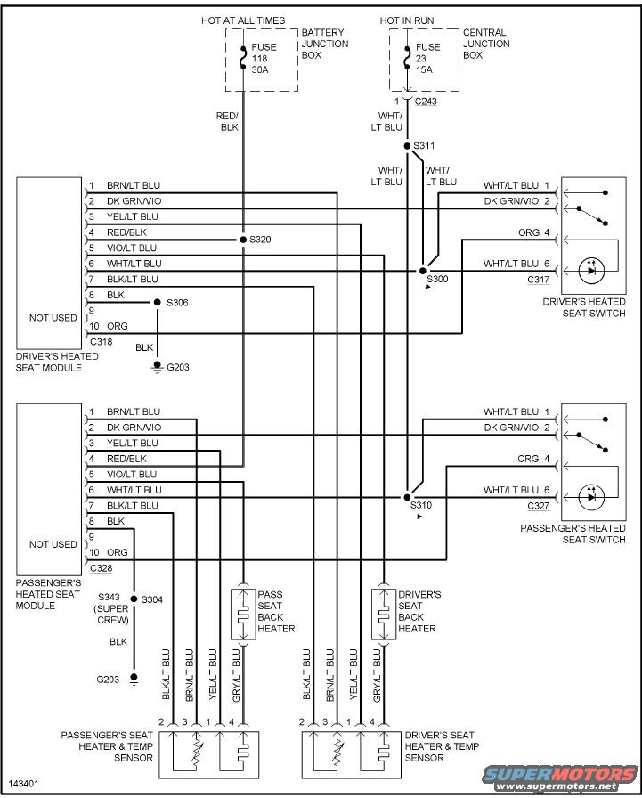
Reference · 1992-1996 BroncoAll 411 wiring diagrams
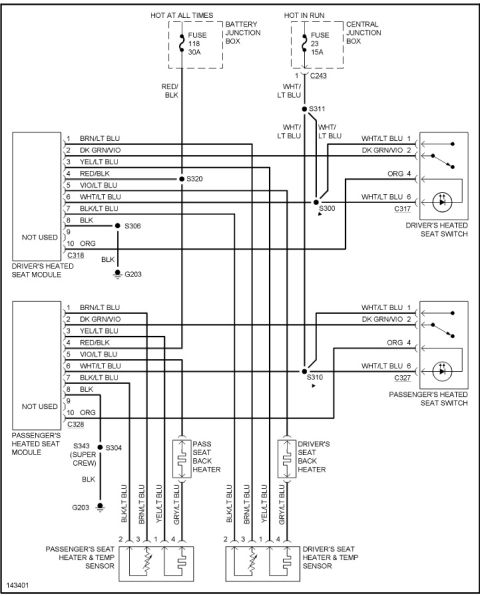














Factory heated-seat wiring diagram showing driver and passenger heated-seat modules (C318/C328), switches, seat back/cushion heaters and temp sensors; power on fuse 118 (30A) and fuse 23 (15A).
Part of 1992-1996 Ford Bronco Wiring Diagrams
This is a heated seat wiring diagram (diagram number 143401) covering both the driver's and passenger's heated seat circuits. Power comes from two sources: Fuse 118 (30A) in the Battery Junction Box (hot at all times, RED/BLK wire) and Fuse 23 (15A) in the Central Junction Box (hot in run, WHT/LT BLU wire through connector C243 and splice S311). Each side has a heated seat module (driver's connector C318, passenger's connector C328) with 10 pins including BRN/LT BLU, DK GRN/VIO, YEL/LT BLU, RED/BLK, VIO/LT BLU, WHT/LT BLU, BLK/LT BLU, BLK ground, and ORG wires; pin 9 is not used. Each module connects to a heated seat switch (driver's C317, passenger's C327) with illumination, a seat back heater element, and a seat heater & temp sensor unit (pins 1-4 with BLK/LT BLU, BRN/LT BLU, YEL/LT BLU, and GRY/LT BLU wires). Grounds are at G203 via splices S306 and S304 (splice S343 noted for Super Crew). Other splices shown include S300, S310, S311, and S320. A reader can trace complete circuit paths, wire colors, connector pin assignments, and fuse ratings for diagnosing heated seat problems.
Is this accurate? Sign in to help verify it.
Frequently asked questions
- What fuse powers the heated seats in this diagram?
- Two fuses are shown: Fuse 118 (30A) in the Battery Junction Box, which is hot at all times, and Fuse 23 (15A) in the Central Junction Box, which is hot in run.
- What connectors are used for the heated seat modules and switches?
- The driver's heated seat module uses connector C318 and its switch uses C317. The passenger's heated seat module uses C328 and its switch uses C327. The run-power feed passes through connector C243.
- What wire colors go to the seat heater and temp sensor?
- Both driver's and passenger's seat heater & temp sensors use BLK/LT BLU (pin 2), BRN/LT BLU (pin 3), YEL/LT BLU (pin 1), and GRY/LT BLU (pin 4).
- Where do the heated seat circuits ground?
- Both modules ground at G203 via BLK wires: the driver's module through splice S306, and the passenger's module through splice S304, with splice S343 noted for the Super Crew.
- Which module pin carries battery power?
- Pin 4 of each heated seat module carries the RED/BLK wire from Fuse 118 (30A), joined at splice S320.






No comments yet.