Home/
Registry/
Ford/
Mustang/
1964-1973/
1965 Ford Mustang/
Photo
supermotors.net/registry/media/1007189
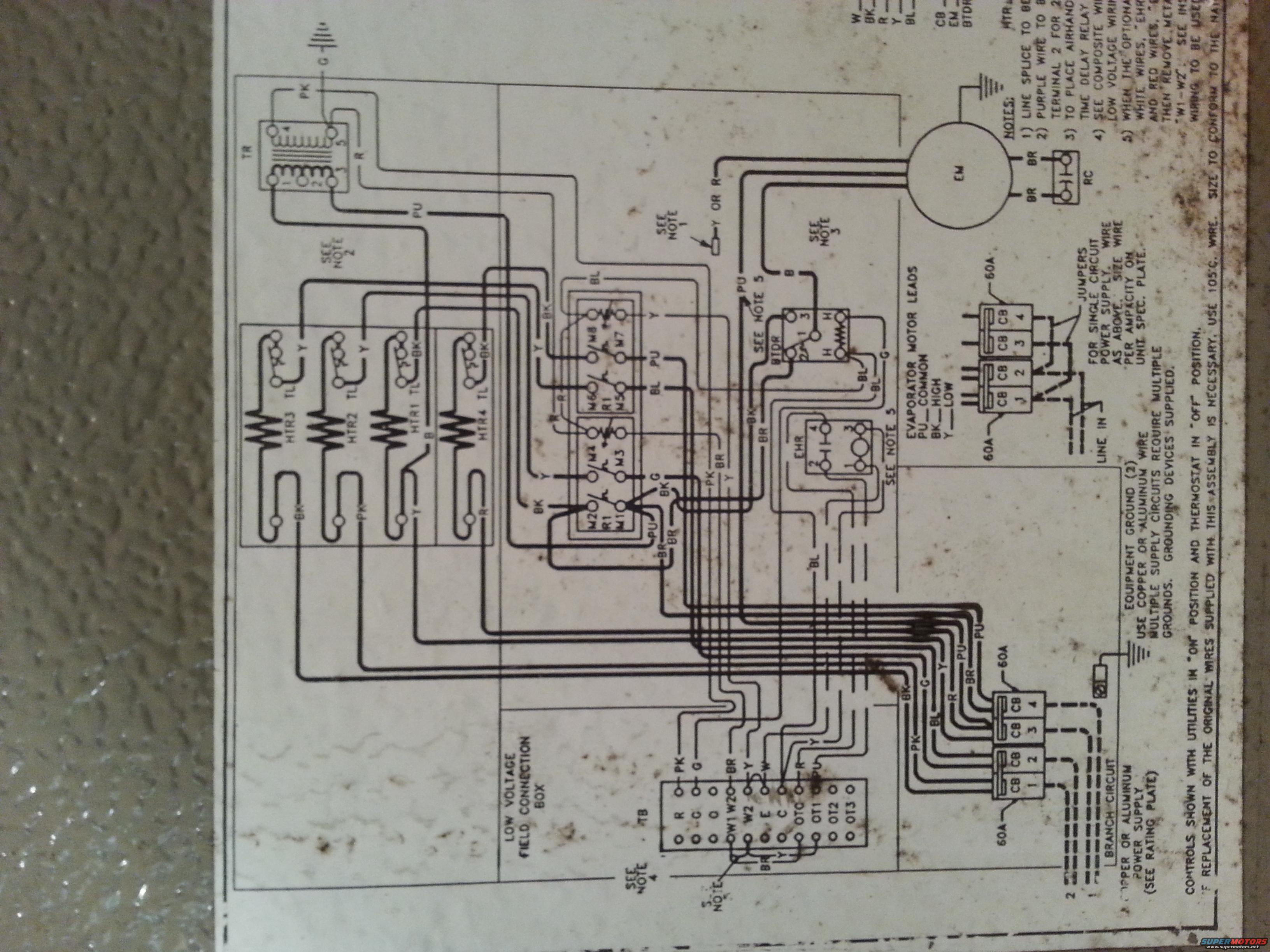
Electric Heat Air Handler Wiring Diagram - HTR, BTDR, EHR, 60A Breakers
Reference · 1964-1973 MustangAll 10 wiring diagrams
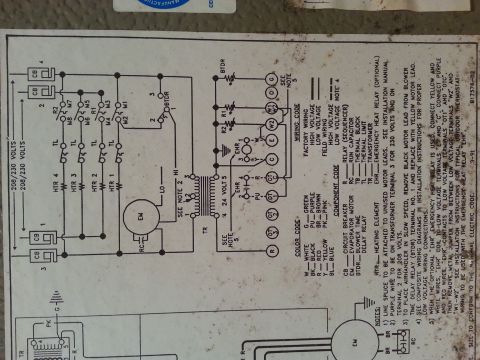
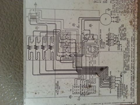
Wiring diagram on an HVAC unit showing motor leads, transformer, contactor and low-voltage field connections.
Part of 1964-1973 Ford Mustang Wiring Diagrams
This document is a schematic wiring diagram for an electric-heat air handler / evaporator unit (HVAC equipment), not an automotive wiring diagram. It shows a low-voltage field connection box with a thermostat terminal board (R, C, W1, W2, E, OT1, OT2, OT3), a control transformer (TR), four electric heater elements with thermal limits (HTR1-HTR4 TL), sequencer/relay contacts (M1-M8, R1), a blower time-delay relay (BTDR), an electric heat relay (EHR), and the evaporator motor (EM) with its run capacitor (RC). Evaporator motor lead colors are identified: purple = common, black = high speed, yellow = low speed. Power distribution shows two banks of 60A circuit breakers (positions 1-4) with jumpers for single-circuit power supply, line-in connections, branch circuits, and instructions for copper or aluminum power supply wiring with equipment grounds. Five installation notes appear along the edge (partially cut off), covering line splices, purple wire connection, time-delay relay placement, composite low-voltage wiring, and optional wiring changes at W1-W2. A footer states controls are shown with utilities on and thermostat off, and that replacement wires must be 105°C rated and sized per national code. Wire color codes (PK, BR, BL, BK, PU, Y, G, R, W) are marked throughout the schematic.
Is this accurate? Sign in to help verify it.
Frequently asked questions
- What are the evaporator motor lead wire colors?
- Per the legend on the diagram: PU (purple) = COMMON, BK (black) = HIGH speed, Y (yellow) = LOW speed.
- What amperage are the circuit breakers in this unit?
- The diagram shows two banks of circuit breakers (positions 1-4) each labeled 60A.
- What thermostat terminals are on the low voltage field connection box?
- The terminal board shows R, C, W1, W2, E, C, OT, OT1, OT2, and OT3.
- What wire must be used if the original wires need replacement?
- The footer states to use 105°C wire, sized to conform to the national code (text partially cut off).
- How is a single-circuit power supply wired?
- The diagram shows jumpers across the circuit breaker banks for single circuit power supply, with wire sized per the ampacity on the unit spec plate.

No comments yet.