Home/
Registry/
Ford/
Mustang/
1964-1973/
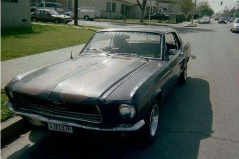
1967 Ford Mustang/
Photo
supermotors.net/registry/media/922975
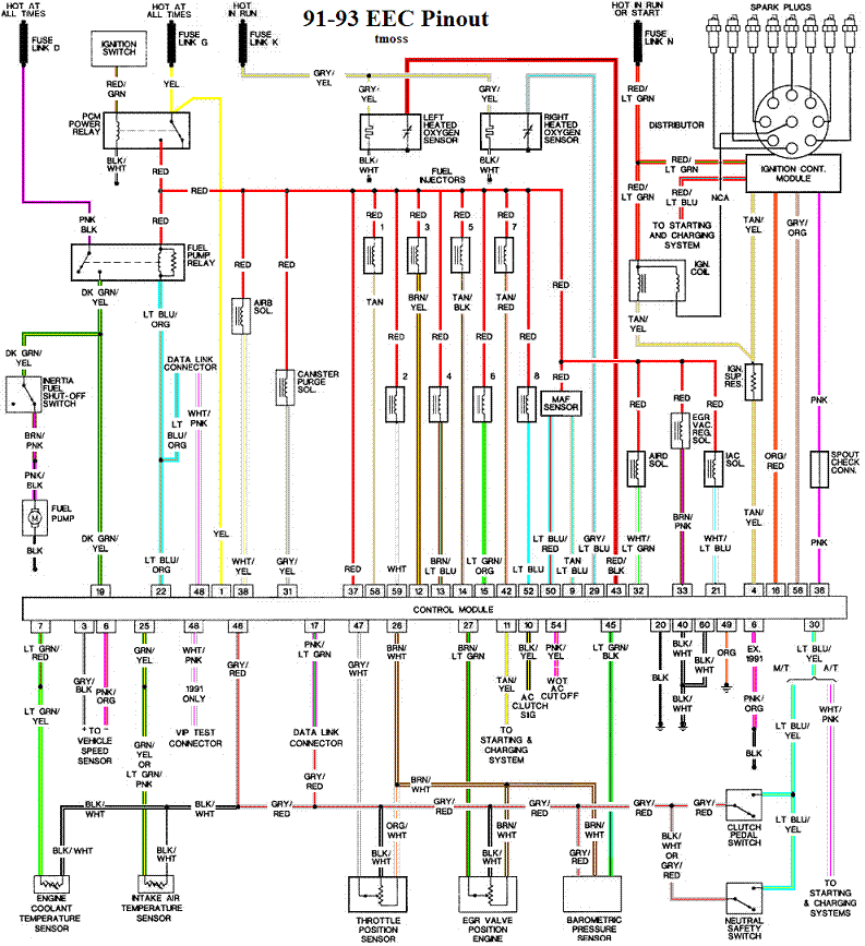
1991-93 Ford Mustang 5.0 EEC-IV Pinout & Wiring Diagram - ECU Pin Colors
Reference · 1964-1973 MustangAll 10 wiring diagrams
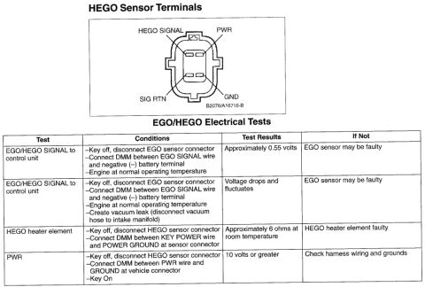
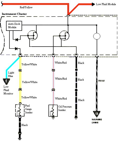
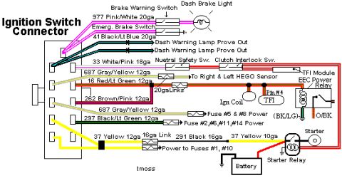
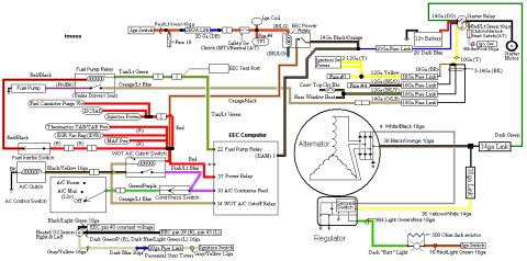
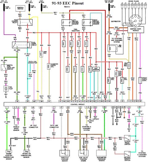
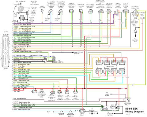
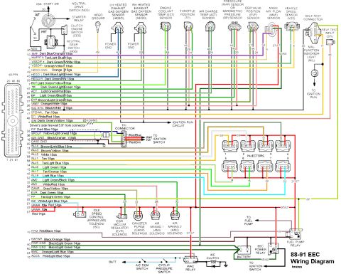
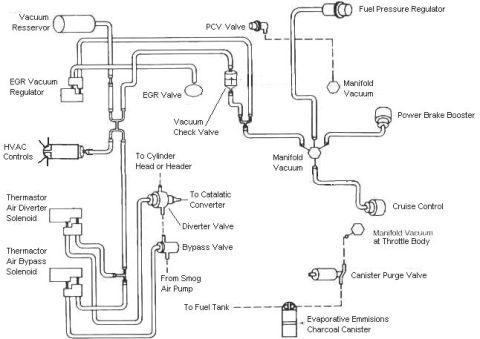
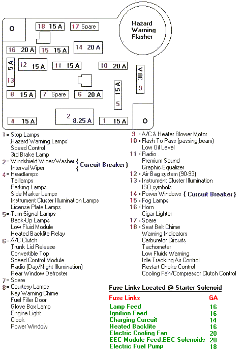
Detailed color-coded 1991-93 EEC engine management wiring diagram showing injectors, sensors, relays, and control-module pinouts.
Part of 1964-1973 Ford Mustang Wiring Diagrams
This document is a color-coded wiring/pinout diagram titled "91-93 EEC Pinout" (credited to "tmoss") for the Ford EEC-IV engine control system, commonly used on 1991-1993 5.0L Mustangs. It shows the EEC control module (ECU) as a central 60-pin band with numbered pins on top and bottom rows, and traces each circuit with its wire color code (e.g., DK GRN/YEL fuel pump to pin 19, TAN/YEL A/C clutch signal to pin 11, LT GRN/BLK barometric pressure sensor to pin 45). Power distribution is shown at the top via fuse links D, G, and N feeding the PCM power relay, fuel pump relay, ignition switch, and ignition module. Components covered include the fuel pump and inertia shut-off switch, left and right heated oxygen sensors, eight numbered fuel injectors, MAF sensor, IAC, AIRB/AIRD solenoids, canister purge and EGR vacuum regulator solenoids, distributor/ignition module with spark plugs, SPOUT check connector, engine coolant and intake air temperature sensors, throttle position sensor, EGR valve position sensor, barometric pressure sensor, data link and VIP test connectors, clutch pedal switch, and neutral safety switch. Notes flag 1991-only wiring (pin 48 WHT/PNK) versus except-1991 wiring (pin 8 PNK/ORG). Useful for diagnosing EEC-IV circuits or wiring a 5.0 engine swap.
This document covers 1991-1993, which may differ from this 1967 Ford Mustang.
Is this accurate? Sign in to help verify it.
Frequently asked questions
- What years does this EEC pinout diagram cover?
- The diagram is titled "91-93 EEC Pinout," covering the 1991-1993 EEC-IV engine control system, with notes distinguishing '1991 ONLY' wiring (pin 48, WHT/PNK) from 'EX. 1991' wiring (pin 8, PNK/ORG).
- Which EEC pin controls the fuel pump, and what is its wire color?
- The fuel pump circuit runs through the fuel pump relay and inertia fuel shut-off switch on a DK GRN/YEL wire to control module pin 19; the pump itself connects via PNK/BLK with a BLK ground.
- What wire colors go to the heated oxygen sensors?
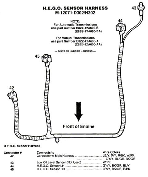
- Both the left and right heated oxygen sensors show GRY/YEL and BLK/WHT wires, with signal wires (GRY/YEL, RED/BLK area) routing to the control module.
- Which sensors are shown on the bottom of the diagram?
- Engine coolant temperature sensor, intake air temperature sensor, throttle position sensor, EGR valve position sensor, and barometric pressure sensor, plus the data link connector, VIP test connector, clutch pedal switch, and neutral safety switch.
- How is the diagram powered at the top?
- Power comes from fuse link D (hot at all times) to the fuel pump relay circuit, the ignition switch feeding the PCM power relay (RED/GRN), fuse link G (hot at all times), a hot-in-run fuse link to the oxygen sensor heaters, and fuse link N (hot in run or start) feeding the ignition/distributor circuit on RED/LT GRN.

No comments yet.