Home/
Registry/
Ford/
Mustang/
1964-1973/
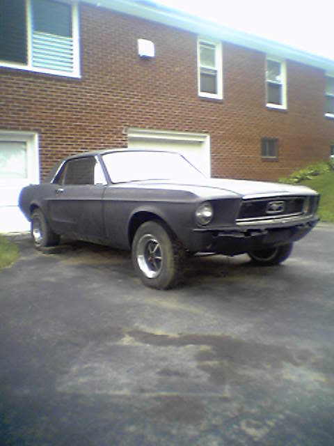
1967 Ford Mustang/
Photo
supermotors.net/registry/media/922977
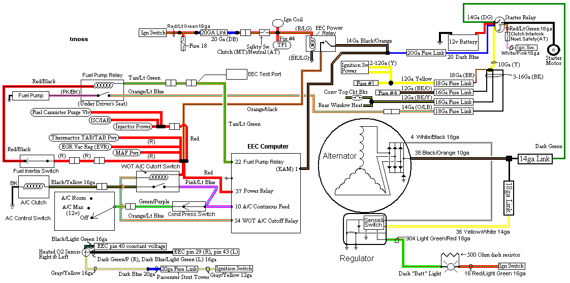
Ford Mustang 5.0 EEC Wiring Diagram - Fuel Pump, Alternator, Fuse Links, A/C
Reference · 1964-1973 MustangAll 10 wiring diagrams
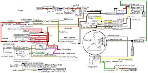
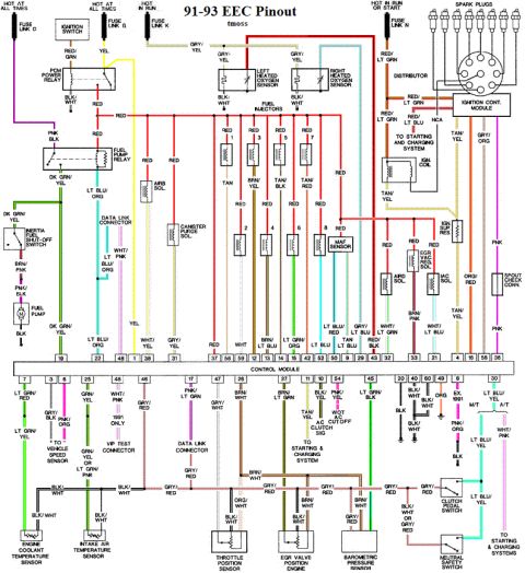
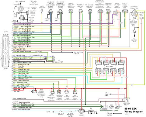
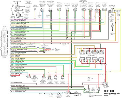
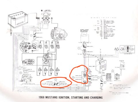
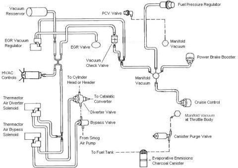
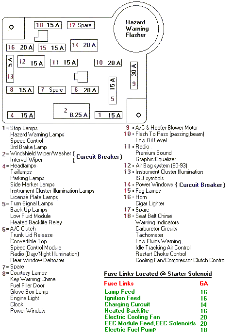
Color-coded wiring diagram of the EEC computer, alternator, regulator, and charging system with labeled wire gauges and colors.
Part of 1964-1973 Ford Mustang Wiring Diagrams
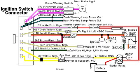
This is a hand-drawn/computer-drawn wiring diagram (credited to "tmoss") covering the fuel pump, alternator/charging, fusible links, ignition switch power distribution, and A/C circuits on a Ford EEC-equipped vehicle. It traces power from the ignition switch through a 20GA fuse link to the EEC Power Relay and TFI module (Pin #4), and shows the clutch (MT)/neutral (AT) safety switch, starter relay, starter motor, and 12v battery wiring with gauge sizes and colors (e.g., 14Ga Dark Green, 10Ga Yellow, 20 Dark Blue). The fuel side shows the Fuel Pump Relay (located under the driver's seat), fuel inertia switch, fuel canister purge valve, ISC/IAB, injector power, Thermactor TAB/TAD, EGR vacuum regulator, and MAF power feeds into the EEC computer (pins 22 Fuel Pump Relay, 37 Power Relay, 10 A/C Continuous Feed, 54 WOT A/C Cutoff Relay). The charging section details the alternator, regulator with sense and switch wires, 14ga and 18ga fuse links, the 500-ohm dash resistor for the "Batt" light, and wires such as 38 Black/Orange 10ga and 36 Yellow/White 14ga. Ignition-switched power feeds (Fuse #1, Fuse #4, convertible top circuit breaker, rear window heat) with their fuse link sizes are also listed, plus heated O2 sensor wiring to EEC pins 29, 40, and 43.
Is this accurate? Sign in to help verify it.
Frequently asked questions
- Where is the fuel pump relay located?
- The diagram notes the Fuel Pump Relay is located under the driver's seat, with a Tan/Lt Green wire and a (PK/BK) wire, feeding the fuel pump through a Red/Black wire via the fuel inertia switch.
- Which EEC computer pins are shown in this diagram?
- Pin 22 Fuel Pump Relay, pin 1 (KAM), pin 37 Power Relay, pin 10 A/C Continuous Feed, pin 54 WOT A/C Cutoff Relay, pin 40 constant voltage for the heated O2 sensors, and pins 29 (right) and 43 (left) for the O2 sensor signals.
- What gauge is the main alternator charge wire?
- The diagram shows a 38 Black/Orange 10ga wire from the alternator, protected by a 14ga fuse link, plus a 4 White/Black 18ga wire and an 18ga link.
- What resistor is used for the dash battery light circuit?
- A 500 Ohm dash resistor is shown in parallel with the dash "Batt" light, on the 904 Light Green/Red 18ga wire from the regulator, connecting to the ignition switch.
- What fuse links protect the ignition-switched power feeds?
- Fuse #1 (12Ga Yellow) uses an 18Ga fuse link, the convertible top circuit breaker (12Ga BK/O) uses a 16Ga fuse link, Fuse #4 (12Ga BK/Y) uses an 18Ga fuse link, and rear window heat (14Ga O/LB) uses an 18Ga fuse link.
No comments yet.