Home/
Registry/
Ford/
Mustang/
1964-1973/
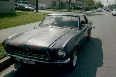
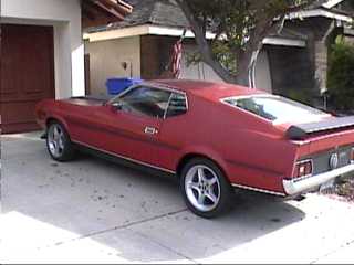
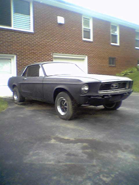
1967 Ford Mustang/
Photo
supermotors.net/registry/media/922973
1988-1991 Ford Mustang 5.0 EEC-IV Wiring Diagram - 60-Pin ECU Pinout & Colors

Reference · 1964-1973 MustangAll 10 wiring diagrams
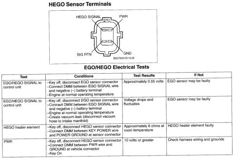
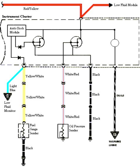
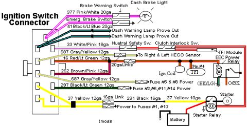
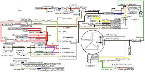
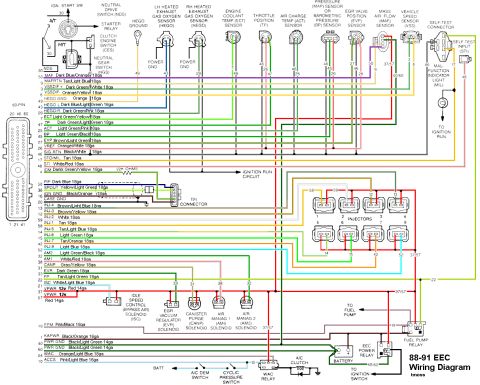
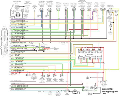
88-91 EEC-IV color engine-management wiring diagram detailing PCM sensor inputs (HEGO, ECT, TPS, MAP, MAF, VSS), fuel injectors, idle speed control, EEC power relay and fuel pump relay with wire colors and gauges.
Part of 1964-1973 Ford Mustang Wiring Diagrams
This document is a Ford EEC-IV engine control wiring diagram labeled "88-91 EEC Wiring Diagram" (credited to "tmoss"). It maps the 60-pin EEC processor connector to all major engine-management circuits, listing each pin number, signal name, and wire color/gauge, e.g., pin 50 MAF (Dark Blue/Orange 18ga), pin 47 TP (Dark Green/Light Green 18ga), pins 37/57 VPWR (Red 14ga), pins 40/60 PWR GND (Black/Light Green 14ga). It shows sensor wiring for the MAF, VSS, left and right HEGO oxygen sensors, ECT, TP, ACT, MAP/BP, and EVP sensors, plus the self-test connector, self-test input (STI), and malfunction indicator light (MIL). Actuator circuits include all eight fuel injectors (pins 58, 59, 12, 13, 14, 15, 42, 52), the idle speed control (ISC) bypass air solenoid, EGR vacuum regulator (EVR), canister purge (CANP), and Air Management 1/2 (AM1/AM2) solenoids. Relay and power distribution circuits are drawn for the EEC power relay, fuel pump relay, WAC (A/C) relay, starter relay, and battery, along with the neutral drive switch, clutch engine switch, neutral gear switch, TFI connector (with 22K-ohm SPOUT detail), A/C demand and cyclic pressure switches. A reader can identify any EEC pin's function and wire color for diagnosing or rewiring an 88-91 Ford 5.0 EFI harness.
This document covers 1988-1991, which may differ from this 1967 Ford Mustang.
Is this accurate? Sign in to help verify it.
Frequently asked questions
- What wire color is the MAF signal on the 88-91 EEC computer?
- Pin 50 (MAF) is Dark Blue/Orange 18ga, and pin 9 (MAF RTN) is Tan/Light Blue 18ga.
- Which EEC pins supply power and ground on the 88-91 harness?
- VPWR 12v is on pins 37 and 57 (Red 14ga), PWR GND is on pins 40 and 60 (Black/Light Green 14ga), and KAPWR is pin 1 (Black/Orange 16ga).
- What are the injector pin numbers and wire colors?
- INJ-1 pin 58 Tan, INJ-2 pin 59 White, INJ-3 Brown/Yellow, INJ-4 Brown/Light Blue, INJ-5 Tan/Light Blue, INJ-6 pin 15 Light Green, INJ-7 pin 42 Tan/Orange, INJ-8 pin 52 Light Blue (all 18ga).
- Which pins connect to the self-test connector?
- The self-test connector uses SIG RTN pin 46 (Black/White), STO/MIL pin 17 (Tan), and STI pin 48 (White/Red 18ga) to the self-test input.
- What solenoids does the EEC control in this diagram?
- The idle speed control (bypass air) ISC solenoid (pin 21), EGR vacuum regulator EVR (pin 33), canister purge CANP (pin 31), Air Management 1 AM1 (pin 38), and Air Management 2 AM2 (pin 41) solenoids.
No comments yet.