Home/
Registry/
Ford/
Mustang/
1964-1973/
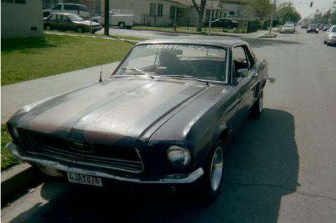
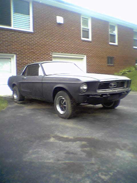
1967 Ford Mustang/
Photo
supermotors.net/registry/media/922972
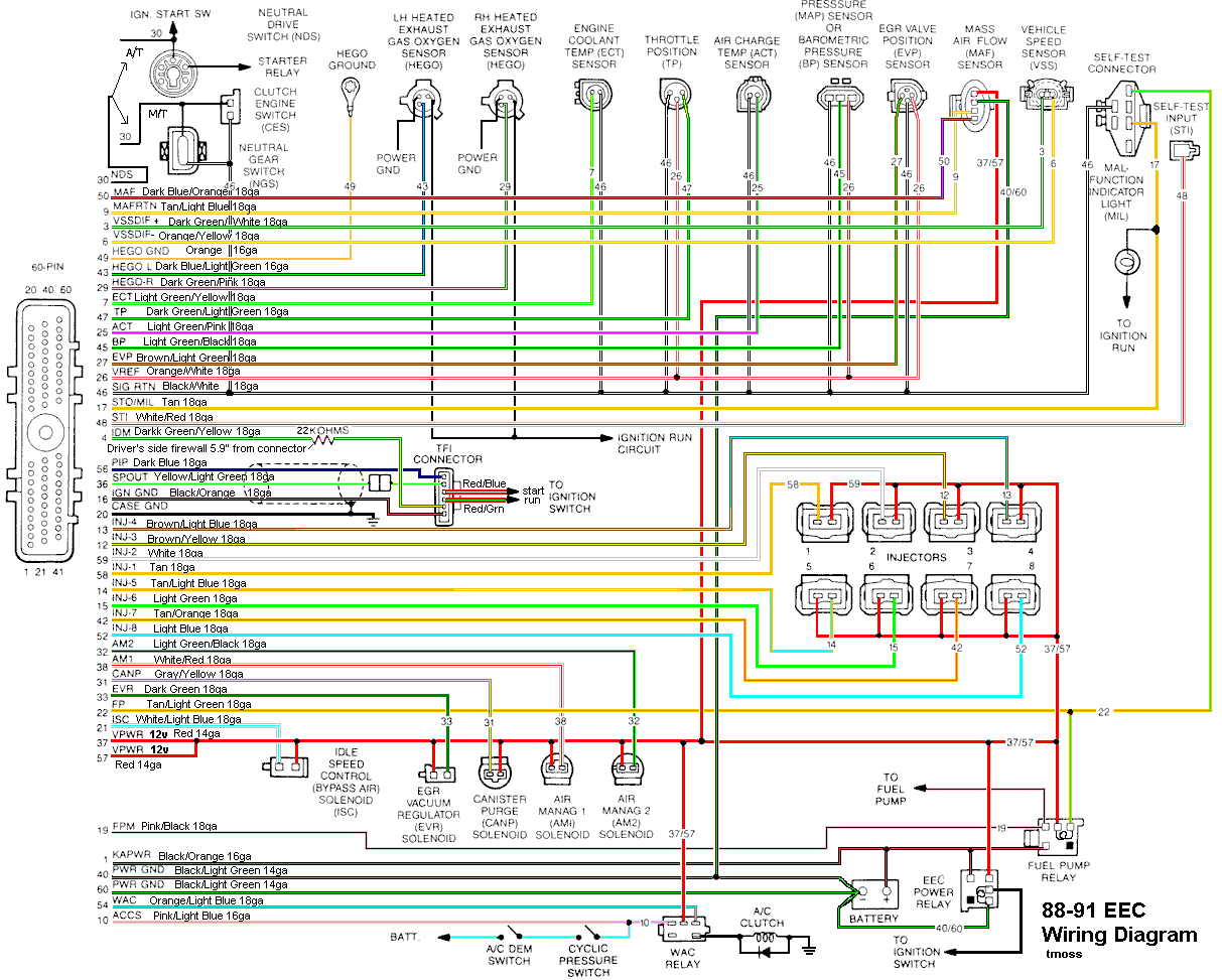
1988-1991 Ford Mustang 5.0 EEC-IV Wiring Diagram - 60-Pin ECU Pinout & Colors
Reference · 1964-1973 MustangAll 10 wiring diagrams
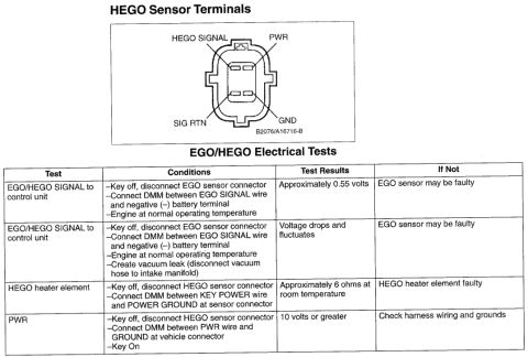
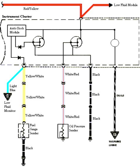
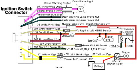
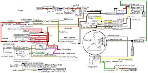
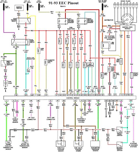
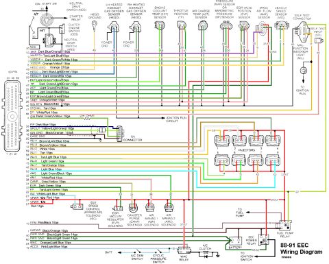
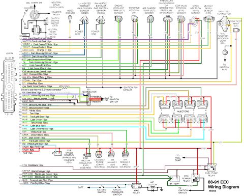
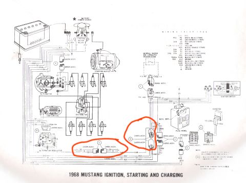
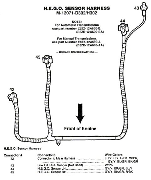
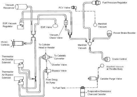
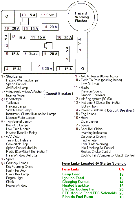
88-91 EEC-IV color engine-management wiring diagram detailing PCM sensor inputs (HEGO, ECT, TPS, MAP, MAF, VSS), fuel injectors, idle speed control, EEC power relay and fuel pump relay with wire colors and gauges.
Part of 1964-1973 Ford Mustang Wiring Diagrams
This document is a color-coded EEC-IV engine control wiring diagram labeled "88-91 EEC Wiring Diagram" by 'tmoss', covering the Ford EEC-IV computer harness (commonly used on 1988-1991 5.0L Mustangs). It shows the 60-pin EEC connector and lists each ECU pin with its signal name, wire color, and wire gauge, e.g., pin 50 MAF Dark Blue/Orange 18ga, pin 46 SIG RTN Black/White 18ga, pins 37/57 VPWR Red 14ga, pins 40/60 PWR GND Black/Light Green 14ga. Sensor connections shown include both heated oxygen sensors (HEGO), engine coolant temp (ECT), throttle position (TP), air charge temp (ACT), MAP/BP sensor, EGR valve position (EVP), mass air flow (MAF), and vehicle speed sensor (VSS), plus the self-test connector, self-test input (STI), and malfunction indicator light (MIL). It also diagrams all eight fuel injectors with their EEC pin numbers (58, 59, 13, 14, 15, 12, 42, 52), the TFI ignition module connector with start/run wiring, the idle speed control (ISC), EGR vacuum regulator (EVR), canister purge (CANP), and air management (AM1/AM2) solenoids, plus the fuel pump relay, EEC power relay, WAC relay, A/C clutch circuit, battery, starter relay, and neutral drive/clutch switch circuits. A reader can trace any EEC-IV circuit by pin number and wire color.
This document covers 1988-1991, which may differ from this 1967 Ford Mustang.
Is this accurate? Sign in to help verify it.
Frequently asked questions
- What are the VPWR and power ground pins on the 88-91 EEC-IV computer?
- VPWR (12v) is on pins 37 and 57 using Red 14ga wire; PWR GND is on pins 40 and 60 using Black/Light Green 14ga wire.
- Which EEC pins control the eight fuel injectors and what are the wire colors?
- INJ-1 pin 58 Tan, INJ-2 pin 59 White, INJ-3 pin 13 Brown/Yellow, INJ-4 pin 14 Brown/Light Blue, INJ-5 pin 15 Tan/Light Blue, INJ-6 pin 12 Light Green, INJ-7 pin 42 Tan/Orange, INJ-8 pin 52 Light Blue (all 18ga).
- What pin and wire color is the MAF signal on this diagram?
- MAF is pin 50, Dark Blue/Orange 18ga, with MAF RTN on pin 9, Tan/Light Blue 18ga.
- Where does the diagram show the IDM resistor located?
- The IDM wire (pin 4, Dark Green/Yellow 18ga) has a 22K OHMS resistor located at the driver's side firewall, 5.9 inches from the connector.
- What are the SPOUT and PIP wire colors for the TFI connector?
- PIP is pin 56, Dark Blue 18ga; SPOUT is pin 36, Yellow/Light Green 18ga; IGN GND is pin 16, Black/Orange 18ga. The TFI connector also has Red/Blue (start) and Red/Grn (run) wires to the ignition switch.
- Which pin controls the fuel pump relay?
- FP is pin 22 (Tan/Light Green 18ga) and the fuel pump monitor FPM is pin 19 (Pink/Black 18ga), connected to the fuel pump relay.
No comments yet.