Home/
Registry/
Ford/
Mustang/
1964-1973/
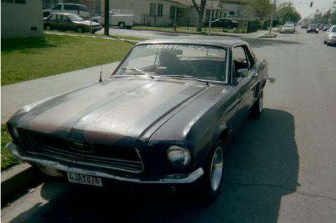
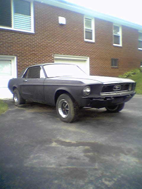
1967 Ford Mustang/
Photo
supermotors.net/registry/media/922978
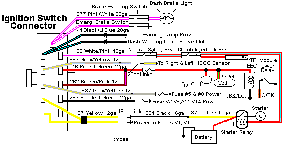
Ford Mustang Ignition Switch Connector Wiring Diagram - Wire Colors & Circuits
Reference · 1964-1973 MustangAll 10 wiring diagrams
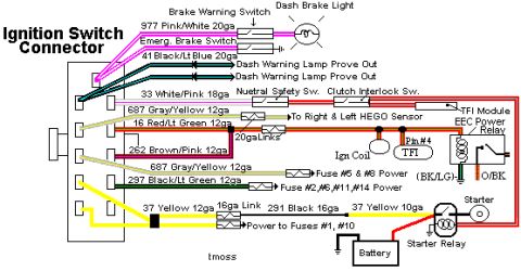
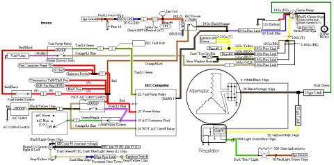
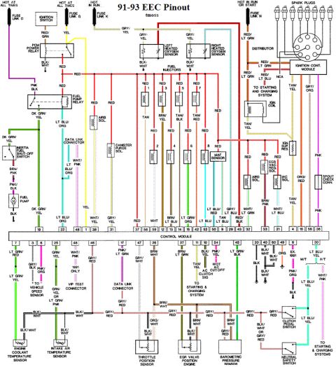
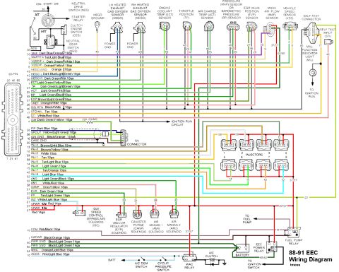
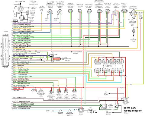
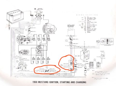
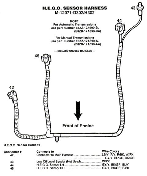
Wiring diagram of the ignition switch connector showing color-coded circuits, wire gauges, TFI module, fuses and starter relay.
Part of 1964-1973 Ford Mustang Wiring Diagrams
This document is a color-coded wiring diagram of the ignition switch connector for a Ford vehicle, showing each wire leaving the ignition switch by circuit number, color, and gauge. It maps circuit 977 Pink/White 20ga to the brake warning switch, emergency brake switch, and dash brake light; circuit 41 Black/Lt Blue 20ga to the dash warning lamp prove-out; and circuit 33 White/Pink 18ga to the neutral safety switch and clutch interlock switch. Run/ignition power circuits include 687 Gray/Yellow 12ga (feeding the right and left HEGO sensors via 20ga fusible links, plus fuse panel positions #5 and #8), 16 Red/Lt Green 12ga, and 262 Brown/Pink 12ga, which route to the ignition coil, TFI module (Pin #4), and EEC power relay, with (BK/LG) and O/BK wire notations at the relay. Circuit 297 Black/Lt Green 12ga powers fuses #2, #6, #11, and #14. Battery/start feed circuit 37 Yellow 12ga connects through a 16ga fusible link and 291 Black 16ga to the starter relay, battery, and starter, and a 37 Yellow 10ga wire supplies power to fuses #1 and #10. The diagram is signed 'tmoss'.
Is this accurate? Sign in to help verify it.
Frequently asked questions
- What wire feeds the neutral safety switch and clutch interlock switch from the ignition switch?
- Circuit 33, a White/Pink 18ga wire, runs from the ignition switch connector to the neutral safety switch and clutch interlock switch.
- Which ignition switch wire powers the HEGO (oxygen) sensors?
- The 687 Gray/Yellow 12ga wire feeds the right and left HEGO sensors through 20ga fusible links.
- Which fuses are powered by the 297 Black/Lt Green 12ga wire?
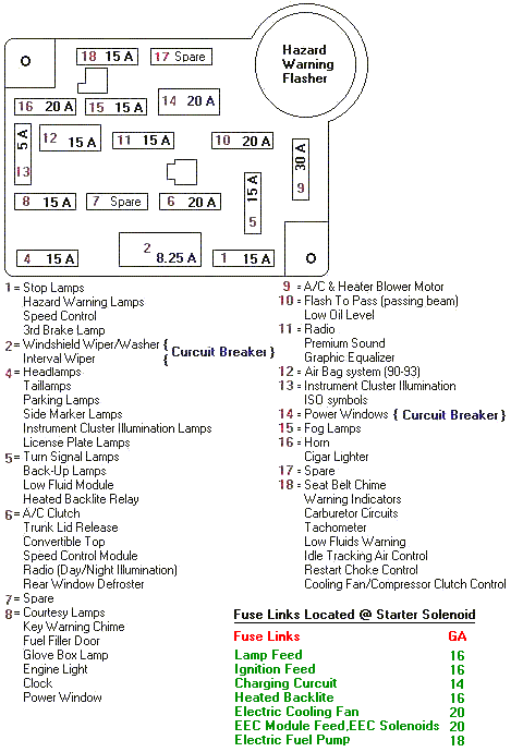
- The 297 Black/Lt Green 12ga circuit supplies power to fuses #2, #6, #11, and #14, while a separate 687 Gray/Yellow 12ga wire powers fuses #5 and #8.
- How does power reach the TFI module and EEC power relay?
- Ignition-switched power routes through the ignition coil/TFI circuit to Pin #4 of the TFI module and to the EEC Power Relay, which shows (BK/LG) and O/BK wire notations.
- What circuit connects the ignition switch to the starter relay and battery?
- Circuit 37 Yellow 12ga runs through a 16ga fusible link and a 291 Black 16ga wire to the starter relay and battery, and a 37 Yellow 10ga wire also supplies power to fuses #1 and #10.
No comments yet.