1968 Ford Mustang Ignition, Starting & Charging Wiring Diagram + Color Codes
Reference · 1964-1973 MustangAll 10 wiring diagrams
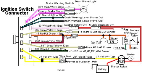
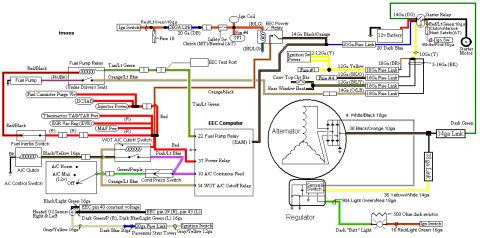
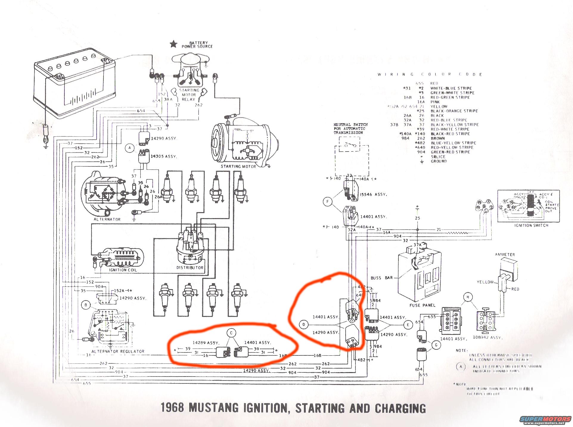
1968 Mustang ignition/starting/charging wiring diagram: battery, starter relay, alternator/regulator, ignition coil, fuse panel, ammeter with full wire color-code chart.
Part of 1964-1973 Ford Mustang Wiring Diagrams
This document is a scanned factory-style wiring diagram titled "1968 Mustang Ignition, Starting and Charging." It illustrates the complete ignition, starting, and charging circuits for the 1968 Ford Mustang, showing the battery, starting motor relay, starting motor, alternator, alternator regulator, ignition coil, distributor, spark plugs, neutral safety switch (for automatic transmission), ignition switch, buss bar, fuse panel, and ammeter. A wiring color code legend on the right identifies each numbered circuit's wire color (e.g., 655 red, 16 red-green stripe, 16A pink, 21 yellow, 26 black, 32 red-blue stripe, 37 black-yellow stripe, 262 brown, 904 green-red stripe, plus splice and ground symbols). Circled letters A through H mark connectors, with wiring harness assembly part numbers such as 14290, 14305, 15546, 14401, 14289, and 10B942 labeled at connection points. Notes state that all connectors are black unless otherwise specified and that asterisked wire functions are not applicable to this circuit. Two areas have been circled in red by the uploader, highlighting connectors C and D between the 14289/14401 and 14401/14290 harness assemblies, likely the area of interest for a repair. Readers can trace wire circuit numbers and colors between all major ignition and charging components.
Is this accurate? Sign in to help verify it.
Frequently asked questions
- What wire color is circuit 16A on a 1968 Mustang?
- Per the wiring color code legend, circuit 16A is pink; circuit 16 (and 16B) is red-green stripe.
- What color is the main battery/charging circuit 655?
- Circuit 655 is red according to the wiring color code table.
- What do the circled letters on the diagram mean?
- A note states that all circled letters (A through H) shown indicate connectors, and unless otherwise specified all connectors are black.
- Which components are covered in this diagram?
- It covers the battery, starting motor relay, starting motor, alternator, alternator regulator, ignition coil, distributor, neutral switch for automatic transmission, ignition switch, buss bar, fuse panel, and ammeter.
- What harness assembly part numbers connect at the ignition circuits?
- Assemblies labeled include 14290, 14305, 15546, 14401, 14289, and 10B942.
No comments yet.