Home/
Registry/
Ford/
Bronco/
1980-1986/
1986 Ford Bronco/
Photo
supermotors.net/registry/media/1018308
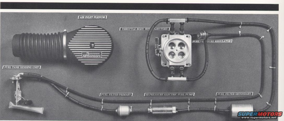
AirSensors TBI Fuel Flow Path Diagram - EFI Fuel System Component Layout
Reference · 1980-1986 BroncoAll 28 manual pages
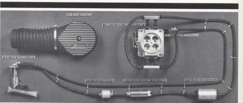

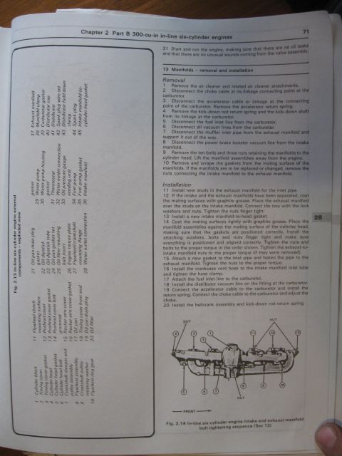
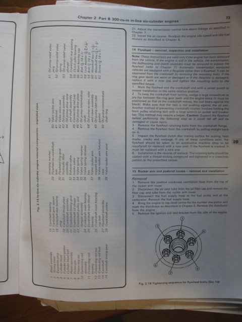
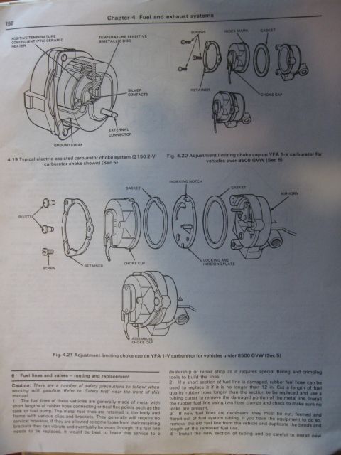
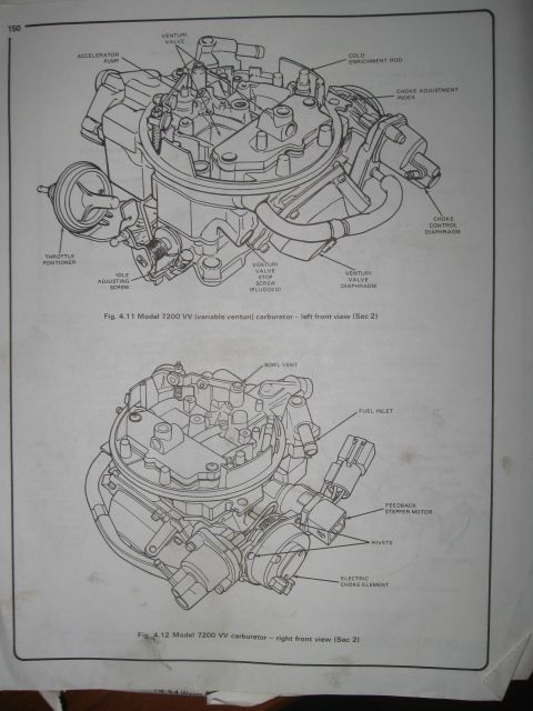
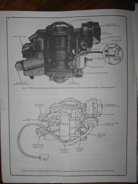








Component-identification photo labeling fuel injection parts such as the air inlet plenum, throttle body with injectors, fuel pressure regulator, pump and filters.
Part of 1980-1986 Ford Bronco Manual Pages
This document is a black-and-white photograph of a display board showing the complete fuel flow path for an AirSensors electronic (throttle body) fuel injection system. All major components are physically mounted on the board, connected by fuel hoses, with printed callout labels identifying each part. Components shown and labeled include: the AIR INLET PLENUM (a finned air cleaner assembly with flexible intake duct, bearing the AiRSensors logo), the THROTTLE BODY WITH INJECTORS (a four-bore throttle body unit), the FUEL PRESSURE REGULATOR mounted at the throttle body, the FUEL TANK SENDING UNIT with in-tank pickup, the FUEL FILTER-PRIMARY, the HI-PRESSURE ELECTRIC FUEL PUMP, and the FUEL FILTER-SECONDARY. The hose routing illustrates the flow of fuel from the tank sending unit through the primary filter, the high-pressure electric pump, and the secondary filter to the throttle body injectors, with a return line from the fuel pressure regulator. A reader can learn the order of components in the AirSensors TBI fuel delivery circuit and how the supply and return lines are routed, which is useful when installing or troubleshooting this aftermarket fuel injection kit. No year, model, part numbers, or specifications are printed on the document itself.
Is this accurate? Sign in to help verify it.
Frequently asked questions
- What components make up the AirSensors fuel injection fuel flow path?
- The labeled components are the fuel tank sending unit, fuel filter-primary, hi-pressure electric fuel pump, fuel filter-secondary, throttle body with injectors, fuel pressure regulator, and air inlet plenum.
- In what order does fuel flow through the AirSensors system?
- As shown by the hose routing, fuel travels from the fuel tank sending unit through the primary fuel filter, then the hi-pressure electric fuel pump, then the secondary fuel filter, and on to the throttle body with injectors, where a fuel pressure regulator is mounted.
- Does the AirSensors system use one fuel filter or two?
- Two filters are shown: a primary fuel filter located before the electric fuel pump and a secondary fuel filter located after the pump.
- What kind of fuel pump does this system use?
- A hi-pressure electric fuel pump, mounted in-line between the primary and secondary fuel filters.
- Where is the fuel pressure regulator located?
- The fuel pressure regulator is mounted on the throttle body assembly, with a return line routed back toward the tank side of the system.






No comments yet.