1988 Ford Bronco Clutch Pedal & Master Cylinder Pushrod Removal - Manual Page
Reference · 1987-1991 BroncoAll 95 service procedures





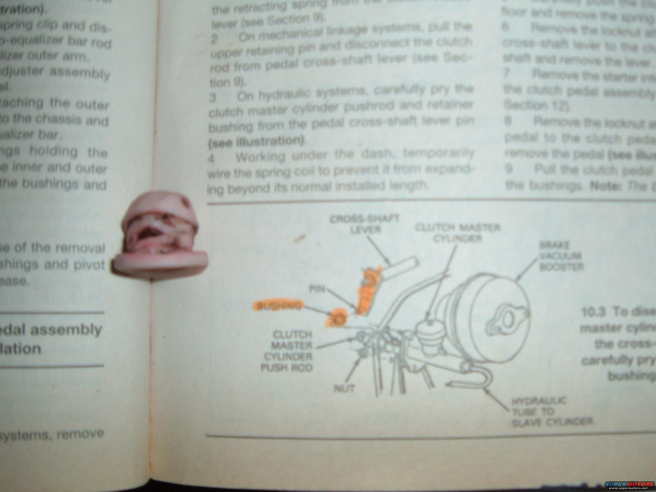
Service manual page giving step-by-step clutch pedal and master cylinder removal with a labeled underdash figure.
Part of 1987-1991 Ford Bronco Service Procedures
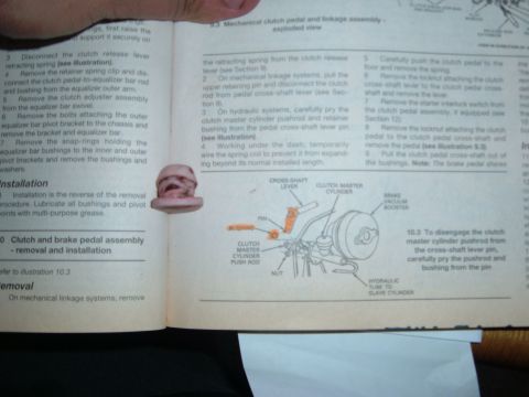
This is a photographed page from a Haynes-style automotive repair manual covering clutch pedal assembly removal and installation, most likely for a Ford truck/Bronco application. The visible numbered procedure steps explain how to disconnect the clutch linkage: on mechanical linkage systems, pulling the upper retaining pin and disconnecting the clutch rod from the pedal cross-shaft lever; on hydraulic systems, carefully prying the clutch master cylinder pushrod and retainer bushing from the pedal cross-shaft lever pin. Step 4 advises working under the dash and temporarily wiring the spring coil to prevent it from expanding beyond its normal installed length. Partially visible steps 6-9 in the right column describe removing locknuts, the cross-shaft lever, the starter interlock (clutch pedal assembly, Section 12), the clutch pedal, and pulling the pedal from the bushings. A labeled illustration (10.3) shows the clutch master cylinder pushrod connection at the pedal cross-shaft lever, with callouts for the cross-shaft lever, clutch master cylinder, brake vacuum booster, pin, bushing (highlighted), clutch master cylinder push rod, nut, and the hydraulic tube to the slave cylinder. Left-column text about removing the equalizer bar, bushings, and pivot points is cut off at the page edge.
Is this accurate? Sign in to help verify it.
Frequently asked questions
- How do you disconnect the clutch master cylinder pushrod on a hydraulic clutch system?
- Per step 3, carefully pry the clutch master cylinder pushrod and retainer bushing from the pedal cross-shaft lever pin (see illustration 10.3).
- How is the clutch rod disconnected on mechanical linkage systems?
- Per step 2, pull the upper retaining pin and disconnect the clutch rod from the pedal cross-shaft lever (see Section 9).
- What precaution is given for the spring coil when working under the dash?
- Step 4 says to temporarily wire the spring coil to prevent it from expanding beyond its normal installed length.
- What components are labeled in the illustration?
- Cross-shaft lever, clutch master cylinder, brake vacuum booster, pin, bushing, clutch master cylinder push rod, nut, and the hydraulic tube to the slave cylinder.






No comments yet.