Ford Bronco Clutch Linkage & Pedal Assembly Removal - Haynes Manual Pages
Reference · 1987-1991 BroncoAll 95 service procedures
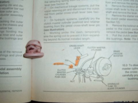


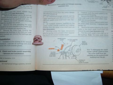








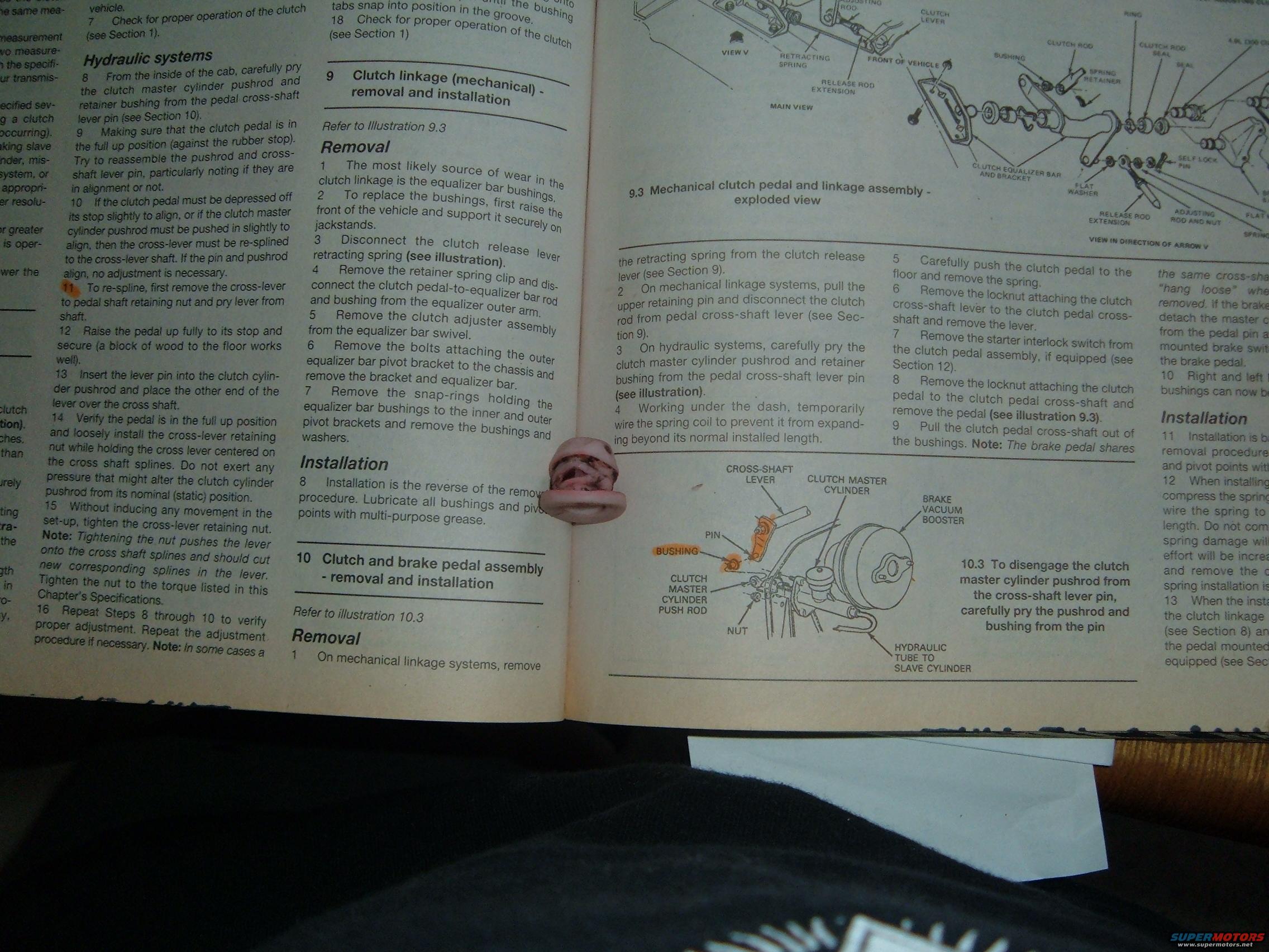
Shop manual spread covering hydraulic clutch systems and mechanical clutch linkage removal/installation; Illustration 10.3 shows clutch master cylinder pushrod disengagement from cross-shaft lever.
Part of 1987-1991 Ford Bronco Service Procedures
This is a photographed two-page spread from a Haynes-style repair manual covering clutch service procedures for a Ford truck/Bronco. The left page finishes a hydraulic clutch pushrod adjustment procedure (Steps 7-16), explaining how to verify alignment of the clutch master cylinder pushrod with the pedal cross-shaft lever pin and how to re-spline the cross-lever if misaligned. Section 9, 'Clutch linkage (mechanical) - removal and installation,' details replacing the equalizer bar bushings: raising the vehicle, disconnecting the retracting spring, removing the retainer spring clip, adjuster assembly, pivot bracket bolts, and snap-rings; installation is the reverse with multi-purpose grease on all bushings and pivot points. Section 10, 'Clutch and brake pedal assembly - removal and installation,' covers both mechanical and hydraulic linkage systems, including wiring the assist spring coil before removal, removing locknuts on the cross-shaft lever and pedal, and the starter interlock switch if equipped; it notes the brake pedal shares the same cross-shaft. Illustration 9.3 shows an exploded view of the mechanical clutch pedal and linkage assembly with labeled parts (clutch rod, bushings, equalizer bar, retracting spring, adjusting rod, etc.), and illustration 10.3 shows how to pry the clutch master cylinder pushrod and bushing from the cross-shaft lever pin, with the brake vacuum booster and hydraulic tube to slave cylinder labeled.
Is this accurate? Sign in to help verify it.
Frequently asked questions
- How do I remove the mechanical clutch linkage (equalizer bar bushings)?
- Raise the front of the vehicle on jackstands, disconnect the clutch release lever retracting spring, remove the retainer spring clip and disconnect the clutch pedal-to-equalizer bar rod and bushing, remove the clutch adjuster assembly from the equalizer bar swivel, unbolt the outer equalizer bar pivot bracket from the chassis, then remove the snap-rings holding the bushings to the inner and outer pivot brackets.
- How do I know if the hydraulic clutch pushrod needs adjustment?
- With the clutch pedal in the full up position against the rubber stop, try to reassemble the pushrod and cross-shaft lever pin. If they align, no adjustment is necessary. If the pedal must be depressed off its stop or the pushrod pushed in slightly to align, the cross-lever must be re-splined to the cross-lever shaft.
- How do I disconnect the clutch master cylinder pushrod from the pedal?
- Carefully pry the clutch master cylinder pushrod and retainer bushing from the pedal cross-shaft lever pin, as shown in illustration 10.3.
- Why must the spring coil be wired before removing the clutch pedal assembly?
- The document says to temporarily wire the spring coil to prevent it from expanding beyond its normal installed length while working under the dash.
- What lubricant should be used when reinstalling the clutch linkage?
- Lubricate all bushings and pivot points with multi-purpose grease.






No comments yet.