Home/
Registry/
Ford/
Bronco/
1992-1996/
1996 Ford Bronco/
Photo
supermotors.net/registry/media/1038089
Rear drum brake adjuster screw and shoe adjusting lever kit proc…

Reference · 1992-1996 BroncoAll 142 service procedures
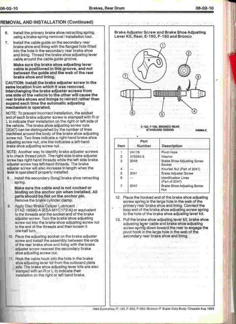




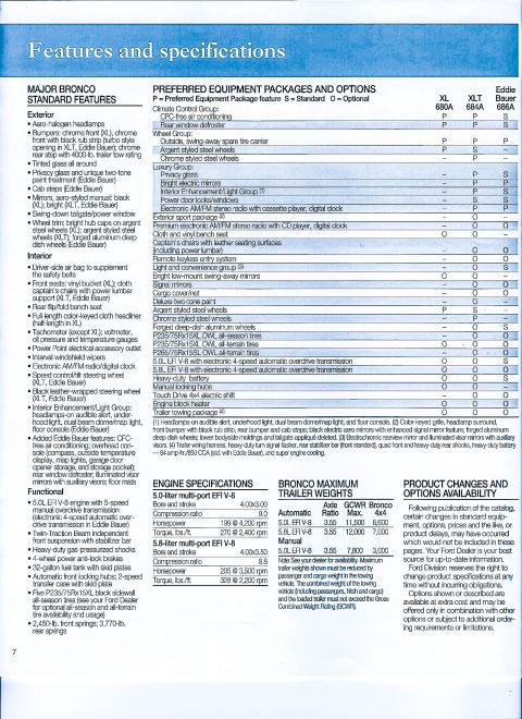
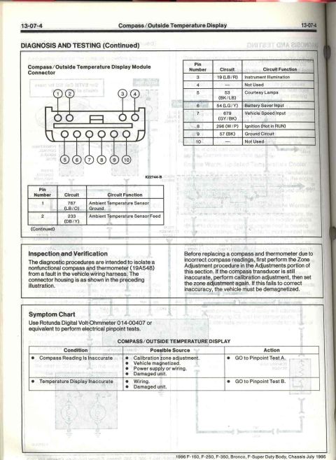



Service manual page 06-02-10, Brakes, Rear Drum, covering adjuster screw and lever cable installation with diagram H4964-C for E-150, F-150 and Bronco.
Part of 1992-1996 Ford Bronco Service Procedures
06-02- 1 0 REMOVAL AND INSTALLATION (Continued) Brakes. Rear Drum 06-02-10 6. Install the primary brake shoe retracting spring using a brake spring removal linstallatlon tool. 7. Install the cable guide on the secondary rear brake shoe and lining with the flanged hole fitted into the hole in the secondary rear brake shoe and lining. Thread the brake shoe adjusting lever cable around the cable guide groove. Make sure the brake shoe adjusting lever cable le positioned in this groove, and not between the guide and the web oi the rear brake shoe and lining. CAUTION: Install the brake adjuster screw In the same location tram which it was removed. lnterchanglng the brake adjuster screws trom one side at the vehicle to the other will cause the rear brake shoes and linings to retract rather than expand each time the automatic adjusting mechanism ls operated. NOTE: To prevent incorrect Installation. the socket end of each brake adjuster screw is stamped with R or L to Indicate their installation on the right or left side of the vehicle. The brake shoe adjusting screw nuts (2047) can be distinguished by the number of lines machined around the body of the brake shoe adjusting screw nut. Two lines indicate a right-hand brake shoe adjusting screw nut; one line indicates a left-hand brake shoe adjusting screw nut. NOTE: Another way to identify brake adjuster screws Is to check thread pitch. The right side brake adjuster screw has right-hand threads while the left side brake adjuster screw has left-hand threads. The brake adjuster screw will also increase in length when the lever is operated if properly installed. 8. Install the secondary (long) brake shoe retracting spring. Make sure the cable and Is not cocked or binding on the anchor pin when Installed. All parts should be flat on the anchor pin. Remove the brake cylinder clarnp. , 9. Apply Disc Brake Caliper Lubricant D7AZ-19590A (ESA.M101 72~A) or equivalent to the threads and the socket end at the brake adjuster screw. Turn the brake shoe adjusting screw nut into the brake shoe adjusting screw nut to the end of the threads and then loosen it one~halt turn. 10. Place the adjusting socket on the brake adjuster screw and install the assembly between the ends of the rear brake shoe and lining with the brake adjuster screw nearest the secondary brake shoe adjusting screw nut. 11. Hack the cable hook into the hole in the brake shoe adjusting lever kit from the outboard plate side. The brake shoe adjusting lever kits are also stamped with an Fl or L to indicate their installation on the right or left hand brake. Brake Adjuster Screw and Brake Shoe Adjusting Lever Kit, Rear, E-150, F-150 and Bronco 0 5-150, 51%. aaouco REAR STANDARD DESIGN mam: . Part Item Number Description 1 2A176 Pivot Hook 2 3725836 Washer 3 2048 Brake Shoe Adjusting Screw Socket 4 Knurled Nul (Part of 2041) 5 2041 Brake Adjuster Screw 6 Identication Lines (Part of 2047) 7 2047 Brake Shoe Adjusting Screw Nut 12. Place the hooked end of the brake shoe adjusting 13. Pull the brake shoe adjusting lever kit. brake shoe screw spring in the large hole in the web of the primary rear brake shoe and lining. Connect the loop end of the brake shoe adjusting screw spring to the hole of the brake shoe adjusting lever kit. g adjusting lever cable and brake shoe adjusting screw spring down toward the rear to engage the pivot hook in the large hole in the web of the secondary rear brake shoe and lining. 1994 Econoline/F- 150. F-250, F-asoi Bronco/F-Super Duly Body/Chassis Aug 1993
Is this accurate? Sign in to help verify it.






No comments yet.