Home/
Registry/
Ford/
Bronco/
1987-1991/
“Eddie Bauer”/
Photo
supermotors.net/registry/media/1054745
Ford Idle Air Control (ISC-BPA) Solenoid Cutaway Schematic - Bronco IAC Valve
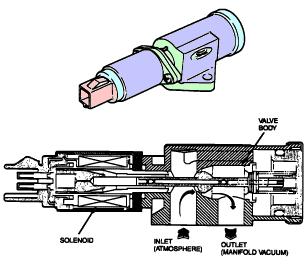
Schematic cross-section of an idle air control solenoid showing the valve body, inlet (atmosphere) and outlet (manifold vacuum) ports.
This document is a schematic illustration of a Ford idle air control style solenoid valve, shown in two views. The upper portion is an external color rendering of the complete solenoid valve assembly, including its electrical connector and mounting bracket/flange. The lower portion is a cutaway cross-section drawing showing the internal construction of the unit. Four callouts identify the major elements: the SOLENOID (the electromagnetic coil section at the left, behind the electrical connector), the VALVE BODY (the housing at the right containing the air passages and valve pintle), the INLET (ATMOSPHERE) port on the underside, and the OUTLET (MANIFOLD VACUUM) port also on the underside. Arrows within the cutaway indicate the airflow path: air enters at the atmospheric inlet, passes through the internal valve chamber controlled by the solenoid-actuated plunger, and exits through the outlet toward manifold vacuum. A reader can learn from this diagram how the solenoid section actuates the valve to meter atmospheric air into the intake manifold, which is how an idle speed control / air bypass solenoid regulates engine idle. The document contains no part numbers, year, model, wire colors, or specifications, only the labeled component illustration.
Is this accurate? Sign in to help verify it.
Frequently asked questions
- What internal components are labeled in this solenoid diagram?
- The cutaway labels the SOLENOID section, the VALVE BODY, the INLET (ATMOSPHERE), and the OUTLET (MANIFOLD VACUUM).
- Which direction does air flow through the valve?
- Air enters through the inlet, which is open to atmosphere, and exits through the outlet, which connects to manifold vacuum, as shown by the flow arrows in the cutaway.
- What do the two illustrations show?
- The top illustration shows the external appearance of the complete solenoid valve assembly with its connector and mounting bracket; the bottom is a cross-sectional cutaway showing the solenoid coil, valve body, and air passages.
- Does this document give any part numbers or specifications?
- No. It is purely an illustrated schematic with component labels; no part numbers, torque values, or electrical specs are shown.
Comments
More from this build














No comments yet.