Home/
Registry/
Ford/
Bronco/
1987-1991/
“Eddie Bauer”/
Photo
supermotors.net/registry/media/1054747
Ford Idle Air Control (IAC) Valve Diagram - Cutaway Schematic & Airflow

Reference · 1987-1991 BroncoAll 111 schematics

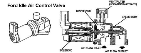
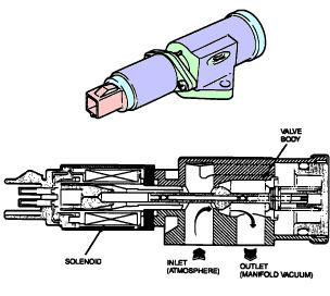
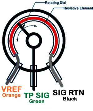
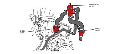












Cutaway schematic of a Ford idle air control valve labeling the solenoid, diaphragm, valve body, vent/filter, and air flow inlet and outlet.
Part of 1987-1991 Ford Bronco Schematics
This document is a labeled schematic of a Ford Idle Air Control (IAC) valve. On the left is a three-quarter perspective illustration of the complete valve assembly, showing its electrical connector, solenoid body, and mounting flange. On the right is a cross-sectional (cutaway) diagram of the valve identifying its internal components. Labeled parts include the solenoid (the coil section that actuates the valve), the diaphragm, the valve body, and the vent/filter, with a note that the vent/filter location may vary between versions. Arrows in the cutaway indicate the air flow path through the valve: air enters at the AIR FLOW INLET at the bottom of the valve body and exits through the AIR FLOW OUTLET. A reader can learn the general internal construction and operating principle of the Ford IAC valve, an electrically driven solenoid moving a valve within the valve body to meter bypass air, and can identify the external appearance of the part for locating it on the engine. The document contains no part numbers, year ranges, engine applications, torque specifications, or electrical pinout information; it is purely a component identification and airflow schematic.
Is this accurate? Sign in to help verify it.
Frequently asked questions
- What internal components are labeled in the Ford IAC valve cutaway?
- The cutaway labels the solenoid, diaphragm, valve body, and vent/filter (with a note that the vent/filter location may vary).
- Which direction does air flow through the Ford idle air control valve?
- Arrows show air entering at the AIR FLOW INLET on the underside of the valve body and exiting at the AIR FLOW OUTLET.
- Is the vent/filter always in the same location on the valve?
- No: the diagram notes 'VENT/FILTER (LOCATION MAY VARY)'.
- What actuates the Ford idle air control valve?
- The cutaway shows a solenoid section that drives the valve mechanism inside the valve body.






No comments yet.