Home/
Registry/
Ford/
Bronco/
1987-1991/
“Eddie Bauer”/
Photo
supermotors.net/registry/media/1054746
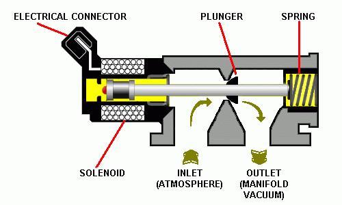
Ford Idle Air Bypass (IAB) Solenoid Cutaway Diagram - Plunger, Spring, Airflow
Reference · 1987-1991 BroncoAll 111 schematics
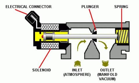
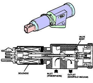













Cross-section diagram of a vacuum control solenoid showing the electrical connector, solenoid coil, plunger and spring with inlet (atmosphere) and outlet (manifold vacuum) ports.
Part of 1987-1991 Ford Bronco Schematics
This document is a labeled cutaway schematic illustration of an idle air bypass (IAB) solenoid valve, as used on Ford fuel-injected engines to control idle speed. The diagram shows the internal construction of the valve in cross-section, with red callout lines identifying five main components: the electrical connector (at the upper left of the housing), the solenoid coil windings (surrounding the yellow core area), the plunger (a horizontal shaft extending through the valve body), and the return spring (shown in yellow at the right end of the assembly). Two airflow paths are indicated with arrows at the bottom of the valve body: an inlet marked 'INLET (ATMOSPHERE)' and an outlet marked 'OUTLET (MANIFOLD VACUUM)', showing that atmospheric air enters the valve and passes through to manifold vacuum when the plunger is retracted. A reader can learn how the idle air control/bypass solenoid works internally: the solenoid, when energized via the electrical connector, moves the plunger against spring pressure to open or modulate the air passage between atmosphere and the intake manifold, thereby regulating engine idle speed. The document contains no part numbers, year, model, or specification text, it is purely an anatomical/functional diagram of the component.
Is this accurate? Sign in to help verify it.
Frequently asked questions
- What are the main internal components of the idle air bypass solenoid shown in this diagram?
- The diagram labels five elements: the electrical connector, the solenoid, the plunger, the spring, and the air passages (inlet and outlet).
- Which direction does air flow through the idle air bypass valve?
- Air enters through the inlet, which is open to atmosphere, and exits through the outlet, which connects to manifold vacuum.
- Where is the return spring located in the IAB solenoid?
- The spring is at the far end of the valve body opposite the electrical connector, acting on the end of the plunger shaft.
- How does the plunger relate to the airflow path?
- The plunger extends from the solenoid through the valve body and sits between the inlet (atmosphere) and outlet (manifold vacuum) passages, so its position controls the bypass airflow.






No comments yet.