Home/
Registry/
Ford/
Bronco/
1987-1991/
“Eddie Bauer”/
Photo
supermotors.net/registry/media/1068914
Ford Vacuum Check Valve Direction Diagram - Airflow & Black Vacuum Side

Reference · 1987-1991 BroncoAll 111 schematics

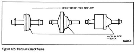












Figure 125 schematic of a vacuum check valve showing three body styles, free-airflow direction, and the black vacuum side.
Part of 1987-1991 Ford Bronco Schematics
This document is Figure 125, titled 'Vacuum Check Valve,' from an automotive reference manual. It is a line-drawing schematic showing three different styles of vacuum check valves used in engine vacuum/emissions systems. An arrow at the top labeled 'DIRECTION OF FREE AIRFLOW' indicates the orientation in which air can pass freely through each valve. A callout pointing to one end of each valve identifies the 'VACUUM SIDE: BLACK,' telling the reader that the black-colored side of the valve is the side that faces the vacuum source. The illustration reference code A6067-D appears in the lower right corner. From this figure, a reader can learn how to correctly orient a vacuum check valve when installing or replacing it: the black side goes toward the vacuum source, and free airflow moves in the direction of the arrow shown. The drawing depicts three common body shapes (a barrel/disc style and two cone/tapered styles) so the identification applies regardless of which physical variant is fitted to the vehicle. The scan was uploaded alongside 1990 Ford Bronco and Mustang emissions diagrams, suggesting it is used for servicing those vehicles' vacuum systems.
Is this accurate? Sign in to help verify it.
Frequently asked questions
- Which side of a Ford vacuum check valve faces the vacuum source?
- According to the diagram, the vacuum side of the check valve is the black side, labeled 'VACUUM SIDE: BLACK.'
- Which direction does air flow through a vacuum check valve?
- The diagram shows an arrow labeled 'DIRECTION OF FREE AIRFLOW,' indicating air flows freely in that one direction through the valve (from the black vacuum side toward the other end).
- How many styles of vacuum check valve are shown in Figure 125?
- Three different vacuum check valve body styles are illustrated, all with the same airflow direction and black vacuum side identification.
- What figure and reference number identifies this diagram?
- It is Figure 125: Vacuum Check Valve, with illustration reference code A6067-D.






No comments yet.