Home/
Registry/
Ford/
Bronco/
1992-1996/
“Eddie Bauer”/
Photo
supermotors.net/registry/media/1006619
Super Duty Seat Adaptor Plate Blueprint v2 - Ford Bronco Seat Swap Dimensions
Reference · 1992-1996 BroncoAll 81 blueprints
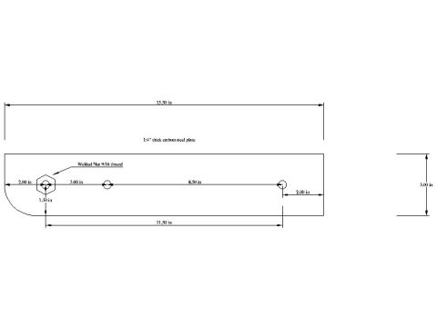
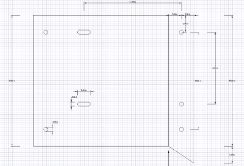
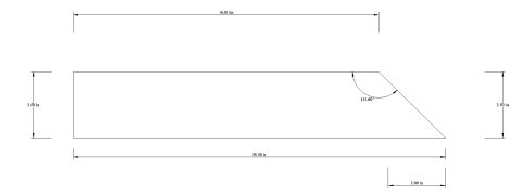
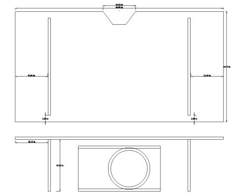











Engineering blueprint of a 1/4-inch carbon steel plate with dimensions, hole locations and a welded nut.
Part of 1992-1996 Ford Bronco Blueprints
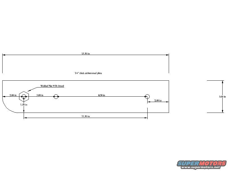
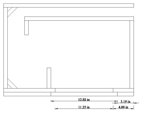
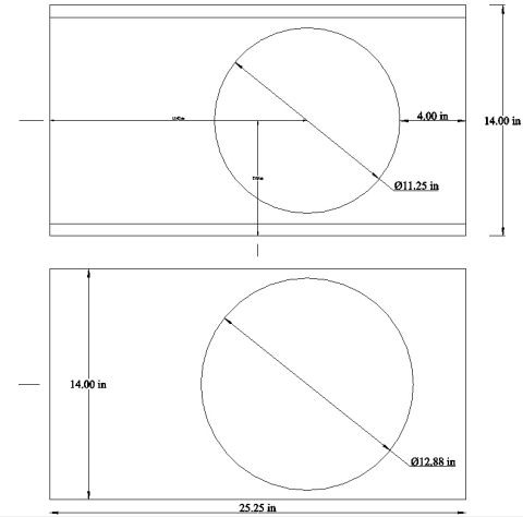
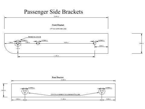
This document is a fabrication blueprint (dimensioned drawing) for a seat adaptor plate, uploaded as "SD Seat Adaptor plate version 2" to accompany a Super Duty seat swap into a 1994 Ford Bronco. The drawing shows a rectangular plate made of 1/4-inch thick carbon steel, 15.50 inches long and 3.00 inches wide (shown in the end view at right). Three mounting points are laid out along the plate's centerline: a hexagonal feature at the left end labeled "Welded Nut 9/16 thread," located 2.00 in from the left edge and 1.50 in from the bottom edge, followed by two circular holes spaced 3.00 in and then 8.50 in apart, with the rightmost hole 2.00 in from the right edge. The overall span between the outermost mounting features is 11.50 in. The lower-left corner of the plate is drawn with a radius/chamfer. A reader can use this drawing to cut and drill a matching adaptor plate for mounting Super Duty seats, including where to weld the 9/16-thread nut. The drawing is undated and does not itself state a vehicle application; it is part of an album that includes side plate, top plate, and 2004 SD power seat wiring documents.
Is this accurate? Sign in to help verify it.
Frequently asked questions
- What material and thickness is the seat adaptor plate made from?
- The drawing calls for 1/4" thick carbon steel plate.
- What are the overall dimensions of the adaptor plate?
- The plate is 15.50 inches long and 3.00 inches wide (per the end view).
- What thread size is the welded nut on the plate?
- The drawing specifies a welded nut with 9/16 thread, located 2.00 in from the left edge and 1.50 in from the bottom edge.
- How are the mounting holes spaced?
- From the welded nut, the first hole is 3.00 in away and the second hole is a further 8.50 in, with the last hole 2.00 in from the right edge. The total span between outer mounting points is 11.50 in.






No comments yet.