Home/
Registry/
Ford/
Bronco/
1978-1979/
“Black Betty”/
Photo
supermotors.net/registry/media/1078433
Hydro-Boost Brake Booster Removal Instructions & Pushrod Measurements - Ford Bronco
Reference · 1978-1979 BroncoAll 48 service procedures
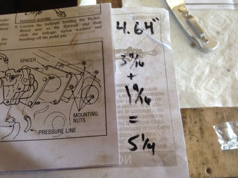
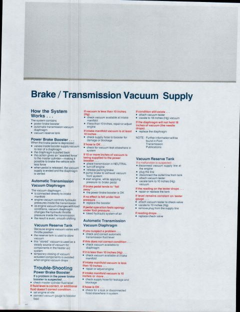
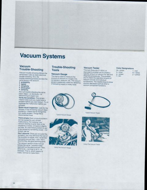
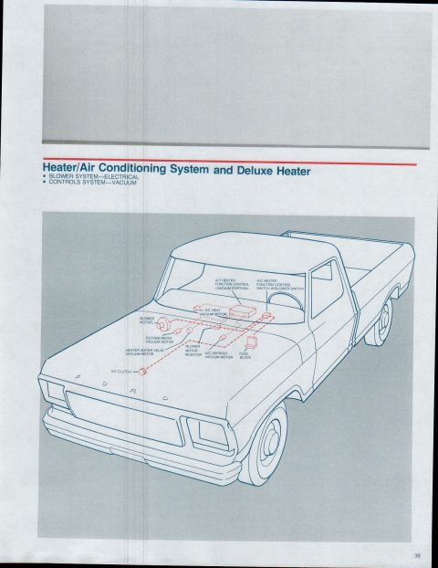
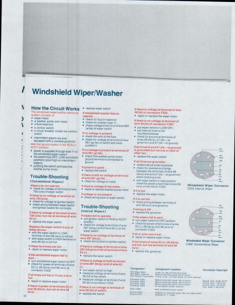


Photo of a service manual page detailing Hydro-Boost unit removal with a labeled figure, alongside handwritten measurements.
Part of 1978-1979 Ford Bronco Service Procedures
This is a photograph of a page from a Hydro-Boost (hydraulic brake booster) installation/removal instruction sheet, uploaded to a 1979 Ford Bronco gallery. The printed portion shows step 6 of a removal procedure: loosening the locknuts that hold the Hydro-Boost unit to the firewall, then sliding the linkage, nylon washers, and bushing off the brake pedal pin. An exploded-view illustration shows the Hydro-Boost unit with callouts identifying the SPACER, MOUNTING NUTS, and PRESSURE LINE, plus a PUSHROD BUSHING label at the top of the page. On the adjacent page, the owner has written measurements in marker: 4.64" at the top, and an addition problem reading 3 11/16 + 1 9/16 = 5 1/4, apparently pushrod or linkage length calculations related to the Hydro-Boost installation. A reversed part-number-like string (approximately 83026A-S2) shows through the paper but cannot be confirmed. The document itself carries no year, make, or model identification, so its applicability to the claimed 1979 Bronco cannot be verified or contradicted from the page contents alone.
Is this accurate? Sign in to help verify it.
Frequently asked questions
- How do you remove the Hydro-Boost unit from the firewall?
- Per step 6 of the instructions, loosen the locknuts holding the Hydro-Boost unit to the firewall, then slide the linkage, nylon washers, and bushing off the pedal pin.
- What components are labeled in the Hydro-Boost exploded diagram?
- The diagram calls out the SPACER, MOUNTING NUTS, and PRESSURE LINE, and a PUSHROD BUSHING is labeled at the top of the page.
- What measurements are handwritten on the sheet?
- 4.64 inches is written at the top, and below it an addition: 3 11/16 + 1 9/16 = 5 1/4 (inches).
- What holds the Hydro-Boost linkage to the brake pedal pin?
- The linkage, nylon washers, and a bushing slide onto the pedal pin and are removed by sliding them off after loosening the firewall locknuts.






No comments yet.