Home/
Registry/
Ford/
Bronco/
1992-1996/
“Buckin Bronco”/
Photo
supermotors.net/registry/media/1110758
1996 Ford Bronco Power Distribution Wiring Diagram 13-11 - Fuse 17 Circuit 640
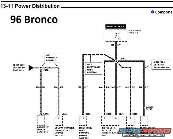
Power distribution wiring diagram for the 1996 Ford Bronco showing mirror, shift-control and instrument-cluster circuits.
This is page 13-11 of the Power Distribution section of a 1996 Ford Bronco wiring diagram set. It shows how power that is hot in START or RUN flows from fuse 17 (10A) in the fuse panel (fuse panel detail on page 13-3) through circuit 640 R/Y (red/yellow wire) to splice S215, which distributes power to several components: the Electronic Shift Control Switch via connector C267 pin 7 (page 34-2, on trucks with electronic shift control), the Instrument Cluster via connectors C250 and C251 pin 13 (pages 60-1, 60-3, 60-5), the Warning Chime Module via connector C280 pin 7 (page 66-1), and the Transmission Control Switch (TCS) via connectors C275M/C275F (pages 29-1, 30-1, on trucks with E4OD or 4R70W transmission). A separate feed from connectors C299 or C206 (page 13-10) goes to splice S302 and supplies circuit 296 W/P (white/purple) to the Day/Night Mirror via C313 (page 125-1) and the Compass/Outside Temperature Module via C314 pin 8 (page 102-1) on trucks with the overhead console. The diagram documents wire circuit numbers, colors, connector numbers, pin numbers, and cross-reference pages.
Is this accurate? Sign in to help verify it.
Frequently asked questions
- What fuse powers the instrument cluster and warning chime module on a 1996 Ford Bronco?
- Fuse 17, a 10A fuse in the fuse panel (fuse panel shown on page 13-3), feeds circuit 640 R/Y, which is hot in START or RUN and powers the instrument cluster (C250/C251 pin 13) and warning chime module (C280 pin 7).
- What wire color is circuit 640 in this diagram?
- Circuit 640 is R/Y (red with yellow stripe). It runs from fuse 17 through splice S215 to the electronic shift control switch, instrument cluster, warning chime module, and transmission control switch.
- Which connectors feed the compass/outside temperature module and day/night mirror?
- Power comes from C299 or C206 (page 13-10) through splice S302 on circuit 296 W/P: connector C313 feeds the day/night mirror (page 125-1) and connector C314 pin 8 feeds the compass/outside temperature module (page 102-1). These apply with the overhead console option.
- What powers the Transmission Control Switch (TCS) on a 1996 Bronco?
- With the E4OD or 4R70W transmission, the TCS receives 640 R/Y power through connectors C275M and C275F; the switch is detailed on pages 29-1 and 30-1.
- When is circuit 640 hot?
- The diagram labels this feed as 'HOT IN START OR RUN,' meaning fuse 17 and circuit 640 R/Y have power only when the ignition is in START or RUN.
Comments
More from this build














No comments yet.