Home/
Registry/
Hyundai/
Genesis Coupe/
2010-2016/
“Coupe”/
Photo
supermotors.net/registry/media/1138892
Hyundai Genesis Coupe Turn Signal & Hazard Lamp Wiring Diagram SD925-1

Reference · 2010-2016 Genesis CoupeAll 79 wiring diagrams
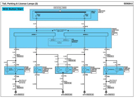
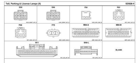
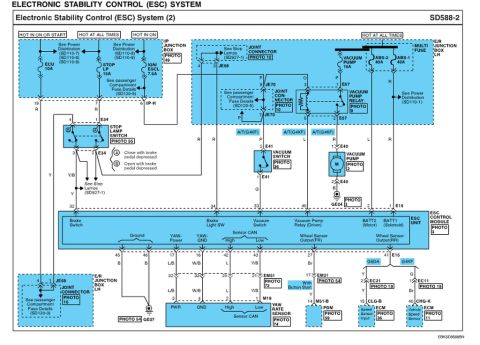
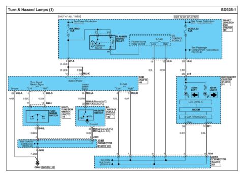
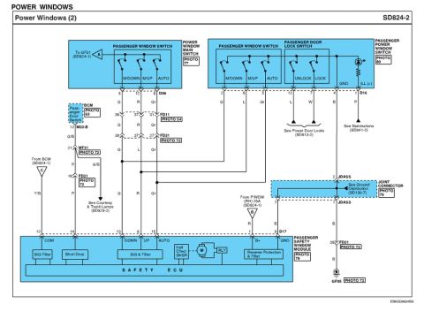
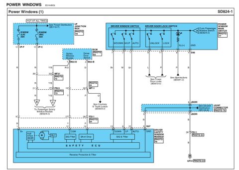
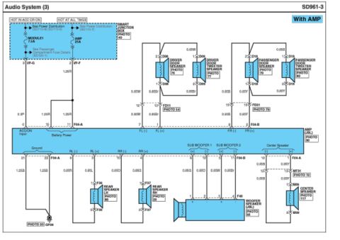
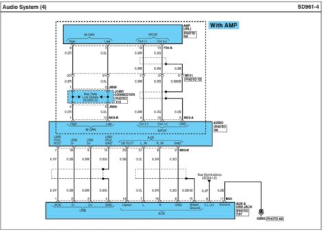








Wiring diagram of turn-signal and hazard-lamp circuits showing fuses, flasher sound relay, multi-function switch and instrument cluster connections.
Part of 2010-2016 Hyundai Genesis Coupe Wiring Diagrams
This document is page SD925-1, "Turn & Hazard Lamps (1)," a factory-style wiring diagram covering the turn signal and hazard lamp circuits. It shows power feeds from the Smart Junction Box: a HAZARD 15A fuse (hot at all times) and a MODULE2 7.5A fuse (hot in ON or START), plus the Flasher Sound Relay and IPS Control Module with B-CAN Low/High lines. Circuits route through connectors I/P-A, I/P-C, I/P-D, M02-A/B/C, M11, M48-L, M06-A/M07-A, JM01, and JM04 to the BCM (turn signal switch signals LH/RH, hazard switch signal, battery power, B-CAN, ground), the Multi-Function Switch (turn signal switch LH/RH), the Hazard Switch on the A/C Control Module (manual and auto A/C variants), and the Instrument Cluster (turn indicators, LED drive IC, MICOM, B-CAN transceiver). Wire gauges/colors such as 0.5R/B, 0.22O, 0.22Y, 0.22W, 0.3L, 0.3R, 0.3P, and 1.25B are labeled, and cross-references point to Power Distribution (SD110-7/8/9), Passenger Compartment Fuse Details (SD120-4), Ground Distribution (SD130-2), Data Link Details (SD200-3), and ground point GM02. A reader can trace turn/hazard circuit wiring, fuse ratings, connector pin numbers, and module interconnections.
Is this accurate? Sign in to help verify it.
Frequently asked questions
- What fuse powers the hazard lamps circuit?
- The HAZARD 15A fuse in the Smart Junction Box, on a HOT AT ALL TIMES feed, powers the hazard circuit; a MODULE2 7.5A fuse (HOT IN ON OR START) also feeds the circuit.
- Where is the hazard switch located in this circuit?
- The hazard switch (OFF/ON) is part of the A/C Control Module (connector M06-A for manual A/C or M07-A for auto A/C, pins 20 and 39), shown as PHOTO 120.
- Which connector pins on the BCM carry the turn signal switch signals?
- Pins 11 (LH, wire 0.22O) and 2 (RH, wire 0.22Y) of connector M02-B on the BCM carry the turn signal switch signals from the multi-function switch via connector M48-L.
- What produces the flasher clicking sound?
- A Flasher Sound Relay inside the Smart Junction Box (pins 30, 85, 86) provides the operation sound, controlled by the IPS Control Module via Flasher Sound Relay Control.
- How do the instrument cluster turn indicators get their signal?
- The instrument cluster (connector M11) receives 0.3P power at pin 29 and communicates over B-CAN High (pin 34, 0.3R) and Low (pin 35, 0.3L) through a B-CAN transceiver, MICOM, and LED drive IC that light the TURN LEFT and TURN LIGHT indicators.

No comments yet.