Home/
Registry/
Hyundai/
Genesis Coupe/
2010-2016/
“Coupe”/
Photo
supermotors.net/registry/media/1137889
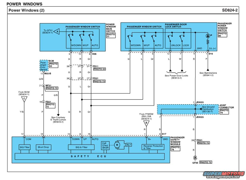
2010 Hyundai Genesis Coupe Passenger Power Window Wiring Diagram SD824-2
Reference · 2010-2016 Genesis CoupeAll 79 wiring diagrams
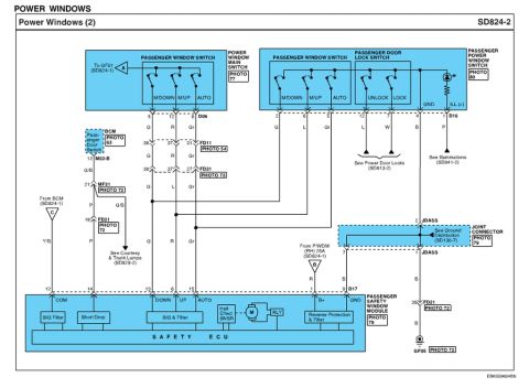








Wiring diagram of the passenger power window system showing the window/lock switches, motor and passenger safety window module.
Part of 2010-2016 Hyundai Genesis Coupe Wiring Diagrams
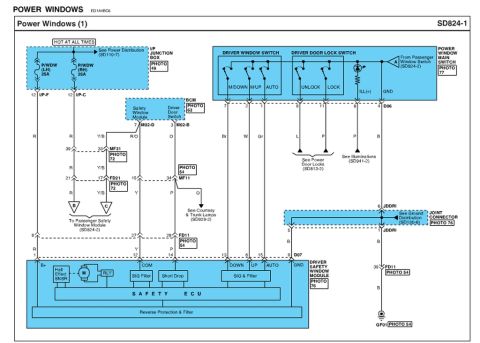
This document is page SD824-2 of a factory-style wiring diagram titled 'Power Windows (2)', covering the passenger-side power window circuit. It shows two passenger window switches: one integrated in the power window main switch (Photo 77) and one in the passenger power window switch assembly (Photo 80), which also contains the passenger door lock switch (UNLOCK/LOCK), ground, and illumination (ILL+) circuits. Switch outputs (M/DOWN, M/UP, AUTO) route through connectors D06 and D16, and intermediate connectors FD11 (pins 38, 37, 31) and FD21 (pins 38, 37, 27) with wire colors G, R/L, and Gr, down to the Passenger Safety Window Module (Photo 79) at connector D17. The module contains a Safety ECU with SIG Filter, Short Drop, SIG & Filter blocks, a Hall Effect sensor, window motor, relay, and reverse protection/filter. Power comes from the P/WDW (RH) 25A fuse (referenced on SD824-1) on a red wire to pin 1 (B+); ground goes via pin 9 through the JDASS joint connector and FD21 pin 39 to ground point GF05. Cross-references include the BCM (Photo 63), Power Door Locks (SD813-2), Illuminations (SD941-2), Courtesy & Trunk Lamps (SD929-2), and Ground Distribution (SD130-7).
Is this accurate? Sign in to help verify it.
Frequently asked questions
- What fuse powers the passenger power window on this diagram?
- The P/WDW (RH) 25A fuse, shown on sheet SD824-1, supplies B+ on a red (R) wire to pin 1 of the Passenger Safety Window Module connector D17.
- What components are inside the Passenger Safety Window Module?
- The module (Photo 79) contains a SIG Filter, Short Drop, SIG & Filter blocks, a Hall Effect sensor (SNSR), the window motor, a relay (RLY), Reverse Protection & Filter, and the Safety ECU.
- What wire colors are used for the passenger window switch signals?
- The M/DOWN, M/UP, and AUTO signals use Green (G), Red (R) or Blue (L), and Gray (Gr) wires through connectors D06, FD11 (pins 38/37/31), and FD21 (pins 38/37/27) to module pins 13 (DOWN), 6 (UP), and 15 (AUTO).
- How is the passenger window module grounded?
- Module pin 9 (GND) on connector D17 runs on a black (B) wire through the JDASS joint connector (Photo 79) and FD21 pin 39 to ground point GF05 (Photo 72). Ground distribution is shown on SD130-7.
- Where are the door lock and illumination circuits for the passenger switch continued?
- The UNLOCK/LOCK switch wires (L and W) continue to Power Door Locks on SD813-2, and the ILL (+) wire (P) continues to Illuminations on SD941-2.

No comments yet.