Home/
Registry/
Ford/
Bronco/
1992-1996/
“Buckin Bronco”/
Photo
supermotors.net/registry/media/1137652
Ford 5.0L Fuel Injector Wiring Diagram - PCM Pinout, E4OD/4R70W (Page 24-3)
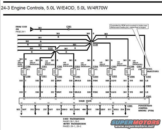
Ford 5.0L engine controls wiring diagram showing eight fuel injector circuits to the PCM with connector and pin identifiers.
This document is page 24-3 of a Ford wiring diagram set covering Engine Controls for the 5.0L engine with either the E4OD or 4R70W automatic transmission. It shows the fuel injector wiring: circuit 361 (Red), which is hot at 12V when the fuel pump/EEC relay is energized, feeds all eight fuel injectors from splices S151 and S149, coming from S122 on page 24-1 and passing through connector C101. Each injector (#1 through #8) has its own connector (C190 through C197) and a dedicated PCM-controlled return wire: 555 T, 556 W, 557 BR/Y, 558 BR/LB, 559 T/BK, 560 LG/O, 561 T/R, and 562 LB, which pass through C101 to specific pins (58, 59, 39, 35, 15, 12, 13, 14) on the Powertrain Control Module connector C185. A callout notes the injectors are controlled by the PCM and mounted in the intake manifold at each intake port. The bottom of the page shows nine transmission control circuits (925 W/Y, 315 P/O, 237 O/Y, 924 BR/O, 923 O/BK, 480 P/Y, 199 LB/Y, 911 W/LG, 224 T/W) leaving the PCM to the E4OD (pages 30-1, 30-2) or 4R70W (pages 29-1, 29-2) transmission diagrams.
Is this accurate? Sign in to help verify it.
Frequently asked questions
- What wire powers the fuel injectors on the 5.0L Ford?
- Circuit 361, a Red wire that carries 12V when the relay is energized. It comes from S122 (page 24-1), passes through connector C101, and splits at splices S151 and S149 to feed all eight injectors.
- What are the injector connector numbers and PCM control wire colors?
- Injector #1 uses C190 with wire 555 T, #2 C191 556 W, #3 C192 557 BR/Y, #4 C193 558 BR/LB, #5 C194 559 T/BK, #6 C195 560 LG/O, #7 C196 561 T/R, and #8 C197 562 LB.
- Which PCM (C185) pins connect to the fuel injectors?
- The injector driver circuits enter PCM connector C185 at pins 58, 59, 39, 35, 15, 12, 13, and 14 for injectors #1 through #8 respectively.
- Where are the fuel injectors mounted according to this diagram?
- A callout states they are controlled by the PCM and mounted in the intake manifold at each intake port, metering fuel to the engine.
- Where do the transmission control wires from the PCM go?
- Nine circuits (925 W/Y, 315 P/O, 237 O/Y, 924 BR/O, 923 O/BK, 480 P/Y, 199 LB/Y, 911 W/LG, 224 T/W) go to the E4OD transmission (pages 30-1, 30-2) or 4R70W transmission (pages 29-1, 29-2).
Comments
More from this build














No comments yet.