Home/
Registry/
Ford/
Bronco/
1992-1996/
“Buckin Bronco”/
Photo
supermotors.net/registry/media/1137665
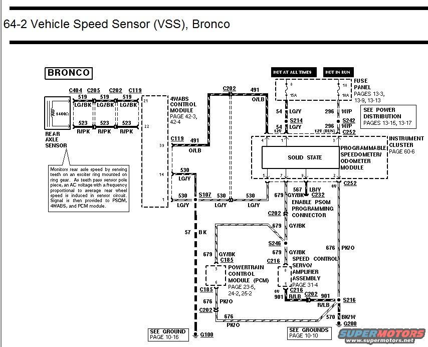
1996 Ford Bronco Vehicle Speed Sensor (VSS) Wiring Diagram - PSOM, 4WABS, PCM
Reference · 1992-1996 BroncoAll 411 wiring diagrams
















Ford Bronco VSS wiring diagram showing rear axle sensor, 4WABS control module and programmable speedometer/odometer module circuits.
Part of 1992-1996 Ford Bronco Wiring Diagrams
This is page 64-2 of a Ford factory wiring diagram set, covering the Vehicle Speed Sensor (VSS) circuit for the Bronco. The diagram shows the rear axle sensor, which (per the note box) monitors rear axle speed via an exciter ring on the ring gear, producing an AC signal proportional to rear wheel speed that feeds the PSOM, 4WABS, and PCM modules. Wiring is traced from the rear axle sensor (circuits 519 LG/BK and 523 R/PK through connectors C404, C205, C202, C119) to the 4WABS Control Module (pages 42-3/42-4), then via circuit 530 LG/Y and splice S107 to the Programmable Speedometer/Odometer Module in the instrument cluster (page 60-6). Power comes from fuse panel fuses (15A hot at all times, 10A hot in run; pages 13-3, 13-9, 13-13) through circuits 54 LG/Y and 296 W/P via splices S214 and S242. The PSOM output signal 679 GY/BK feeds the Powertrain Control Module (via C185) and the Speed Control Servo/Amplifier Assembly (via C216), with 676 PK/O and 901 R/LB circuits also shown. Grounds are G100 (page 10-16) and G200 via 570 BK/W (page 10-10). Circuit 567 LB/Y at C232 is the PSOM programming enable connector.
Is this accurate? Sign in to help verify it.
Frequently asked questions
- What does the rear axle sensor do on the Bronco?
- Per the diagram's note, it monitors rear axle speed by sensing teeth on an exciter ring mounted on the ring gear. As teeth pass the sensor pole piece, an AC voltage with a frequency proportional to average rear wheel speed is induced in the sensor circuit. The signal is provided to the PSOM, 4WABS, and PCM modules.
- What wire colors connect the rear axle speed sensor?
- Circuit 519 is Light Green/Black (LG/BK) and circuit 523 is Red/Pink (R/PK), running through connectors C404, C205, C202, and C119.
- Which circuit carries the vehicle speed signal from the PSOM to the PCM?
- Circuit 679 GY/BK (Gray/Black) carries the speed signal from the Programmable Speedometer/Odometer Module through splice S246 and connector C185 to the Powertrain Control Module, and also to the Speed Control Servo/Amplifier Assembly via C216.
- What fuses power the PSOM in this diagram?
- A 15A fuse that is hot at all times (feeding circuit 54 LG/Y through splice S214) and a 10A fuse that is hot in run (feeding circuit 296 W/P through splice S242). Fuse panel details are on pages 13-3, 13-9, and 13-13.
- Where does the VSS circuit ground?
- The diagram shows ground G100 (see ground page 10-16) via circuit 57 BK, and ground G200 (see grounds page 10-10) via circuit 570 BK/W through splice S216.






No comments yet.