Home/
Registry/
Ford/
Bronco/
1992-1996/
“Buckin Bronco”/
Photo
supermotors.net/registry/media/1149757
Ford 5.8L California Engine Controls Wiring Diagram - Injectors, IAC, PCM Pins

Reference · 1992-1996 BroncoAll 411 wiring diagrams







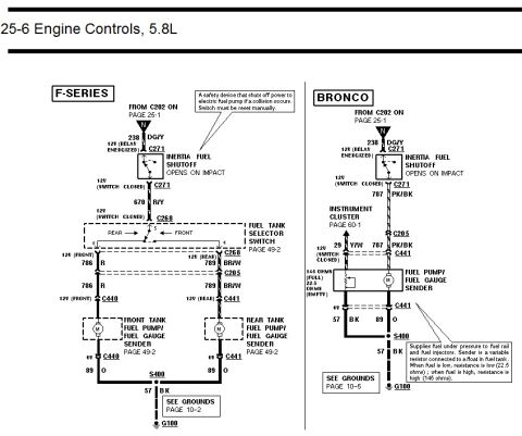











Wiring diagram of 5.8L California engine controls showing fuel injectors, idle air control valve, and secondary air injection solenoid with color-coded wires.
Part of 1992-1996 Ford Bronco Wiring Diagrams
This document is page 25-8 of a Ford electrical/vacuum troubleshooting-style wiring diagram covering Engine Controls for the 5.8L engine with California emissions. It shows how 12-volt relay-energized power on circuit 361 (Red) is distributed from splice S136 (page 25-7) through connector C101M/C101F and splices S149 and S151 to the Secondary Air Injection Diverter (AIRD) Solenoid (connector C1023), the Idle Air Control (IAC) Valve (connector C1007), and all eight fuel injectors (connectors C190 through C197), then continues to C180 on page 25-9. Each injector's control (ground) side wire is identified with its circuit number, wire color, and Powertrain Control Module (PCM) pin at connector C185, for example injector #1 uses circuit 555 T to pin 58 and injector #8 uses 562 LB to pin 14. Explanatory callouts describe the function of the AIRD solenoid, the IAC valve (duty-cycled by the PCM), and the port-mounted fuel injectors. The bottom of the diagram shows PCM outputs leaving C185 to the All-Wheel Drive system (page 34-1), the Vehicle Speed Sensor (pages 64-1), and the E4OD transmission (pages 30-1, 30-2) with their circuit numbers and wire colors. This page is useful for tracing injector, IAC, and AIRD wiring and PCM pin assignments.
Is this accurate? Sign in to help verify it.
Frequently asked questions
- What circuit and wire color supply power to the fuel injectors on the 5.8L California engine?
- Circuit 361, Red (R), which is 12V relay-energized, feeds all eight injectors, the IAC valve, and the AIRD solenoid via splices S149 and S151 from S136 on page 25-7.
- Which PCM pin controls injector #1?
- Injector #1 (connector C190) is controlled through circuit 555, Tan (T), to pin 58 of the PCM at connector C185.
- What does the Idle Air Control (IAC) valve do according to this diagram?
- It controls idle speed during all modes of engine operation. Duty cycles sent by the PCM control a solenoid that opens or closes an air bypass depending on the signal received. It connects via C1007 with circuit 264 W/LB to PCM pin 21.
- What connector is used for the AIRD solenoid and what is its control wire?
- The Secondary Air Injection Diverter (AIRD) Solenoid uses connector C1023, with control circuit 200 BR going to PCM pin 34.
- Where do the PCM outputs at the bottom of this diagram go?
- Pin 42 (784 LB/BK) goes to the All-Wheel Drive circuit on page 34-1; pins 6 and 3 (676 PK/O and 679 GY/BK) go to the Vehicle Speed Sensor on pages 64-1; and pins 38, 52, 51, 55, 49, 53, 30, 32, and 41 go to the E4OD transmission on pages 30-1 and 30-2.






No comments yet.