Home/
Registry/
Ford/
Bronco/
1992-1996/
“Buckin Bronco”/
Photo
supermotors.net/registry/media/1149758
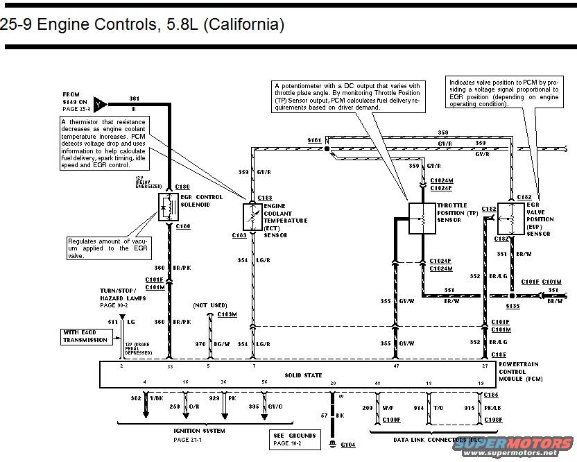
Ford 5.8L California Engine Controls Wiring Diagram - PCM, TP, ECT, EGR Sensors
Reference · 1992-1996 BroncoAll 411 wiring diagrams



















Wiring diagram of 5.8L California engine controls showing EGR control solenoid, ECT sensor, throttle position sensor, and EGR valve position sensor circuits.
Part of 1992-1996 Ford Bronco Wiring Diagrams
This document is page 25-9 of a Ford wiring diagram set covering Engine Controls for the 5.8L engine with California emissions. It shows the wiring between the Powertrain Control Module (PCM) and several engine control components: the EGR Control Solenoid (connector C180), Engine Coolant Temperature (ECT) Sensor (C183), Throttle Position (TP) Sensor (C1024M/C1024F), and EGR Valve Position (EVP) Sensor (C182). Explanatory callouts describe each component's function, the ECT as a thermistor whose resistance decreases with coolant temperature, the TP sensor as a potentiometer indicating throttle plate angle, the EVP sensor as providing a voltage signal proportional to EGR position, and the EGR solenoid as regulating vacuum to the EGR valve. Wire circuits and colors are labeled, including 361 R, 359 GV/R (reference/signal), 360 BR/PK, 354 LG/R, 355 GY/W, 351 BR/W, 352 BR/LG, 511 LG, and 970 DG/W (brake input with E4OD transmission). PCM pin numbers are identified (2, 33, 5, 7, 47, 27 on top; 4, 16, 36, 56, 20, 48, 18, 13 on bottom), with bottom circuits feeding the ignition system (362 V/BK, 259 O/R, 929 PK, 395 GV/O), ground G104 (57 BK), and Data Link Connectors (209 W/P, 914 T/O, 915 PK/LB). Cross-references point to pages 25-8, 90-2, 21-1, and 10-2.
Is this accurate? Sign in to help verify it.
Frequently asked questions
- What PCM pin does the Throttle Position (TP) Sensor signal connect to on the 5.8L California engine?
- The TP sensor signal is circuit 355 GY/W, which passes through connectors C101F/C101M and connects to PCM pin 47. The sensor's reference feed is circuit 359 GV/R via connectors C1024M/C1024F.
- What wire color and circuit is the ECT sensor signal on this diagram?
- The Engine Coolant Temperature (ECT) sensor uses connector C183; its signal is circuit 354 LG/R to PCM pin 7, and it receives 359 GV/R on the other side.
- How does the EGR Valve Position (EVP) sensor connect to the PCM?
- The EVP sensor (connector C182) receives 359 GV/R, sends its signal on circuit 352 BR/LG to PCM pin 27, and its return is 351 BR/W through C101F/C101M to splice S135.
- Where does the PCM get its ground on this diagram?
- PCM pin 20 grounds through circuit 57 BK to ground G104 (see grounds on page 10-2).
- Which PCM pins go to the Data Link Connectors (DLC)?
- Pin 48 (circuit 209 W/P via C199F), pin 18 (914 T/O), and pin 13 (915 PK/LB via C185/C198F) run to the Data Link Connectors, per page reference on the diagram.






No comments yet.