Home/
Registry/
Ford/
Bronco/
1992-1996/
“Buckin Bronco”/
Photo
supermotors.net/registry/media/1149760
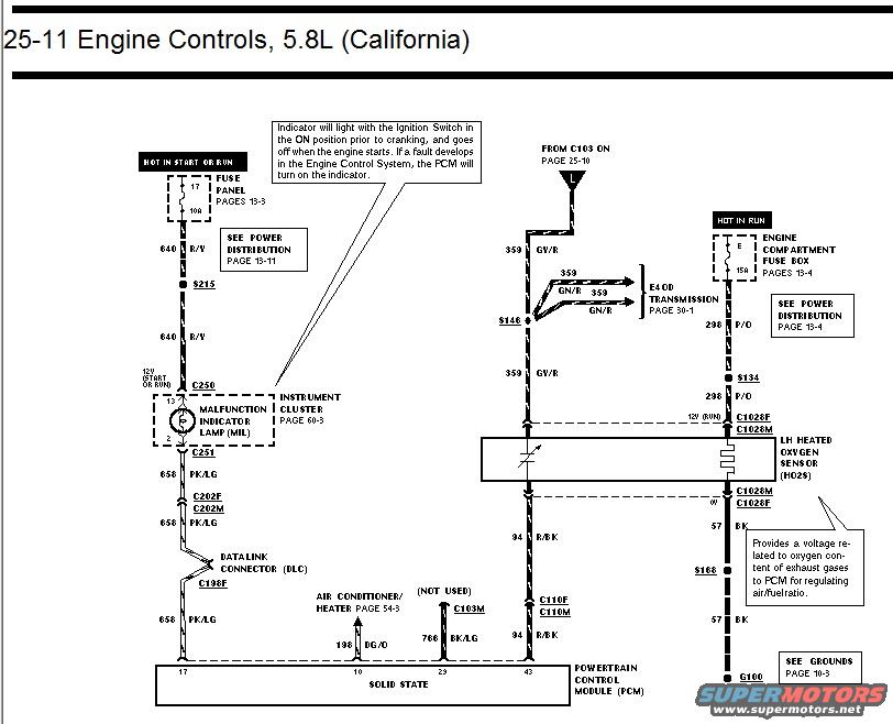
Ford 5.8L California Engine Controls Wiring Diagram 25-11 - MIL, HO2S, PCM
Reference · 1992-1996 BroncoAll 411 wiring diagrams



















Wiring diagram of 5.8L California engine controls showing malfunction indicator lamp, data link connector, and LH heated oxygen sensor circuits.
Part of 1992-1996 Ford Bronco Wiring Diagrams
This document is one page (25-11) of a Ford factory wiring diagram covering Engine Controls for the 5.8L engine with California emissions. It shows circuits feeding the Powertrain Control Module (PCM, pins 17, 10, 23, and 43). The Malfunction Indicator Lamp (MIL) in the instrument cluster is powered by fuse 17 (10A) in the fuse panel (hot in start or run) via circuit 640 R/Y through splice S215 and connector C250; the MIL output runs on circuit 658 PK/LG through connectors C251, C202F/C202M, the Data Link Connector (DLC), and C198F to PCM pin 17. The LH Heated Oxygen Sensor (HO2S) is powered by fuse E (15A) in the engine compartment fuse box (hot in run) via circuit 298 P/O through S134 and connector C1028F/C1028M, with its signal on 94 R/BK to PCM pin 43 and ground on 57 BK through S168 to G100. Circuit 359 GY/R connects from C103 (page 25-10) through splice S146 to the E4OD transmission (359 GN/R, page 30-1). Circuit 198 DG/O links the A/C-heater system to PCM pin 10; 766 BK/LG at C103M is marked not used. Notes explain MIL operation and HO2S function.
Is this accurate? Sign in to help verify it.
Frequently asked questions
- Which fuse powers the Malfunction Indicator Lamp (MIL)?
- Fuse 17, a 10A fuse in the fuse panel, hot in START or RUN, feeding circuit 640 R/Y (see pages 13-3 and Power Distribution page 13-11).
- What wire color is the MIL circuit to the PCM?
- Circuit 658 PK/LG (pink/light green), running through connectors C251, C202F/C202M, the Data Link Connector (DLC), and C198F to PCM pin 17.
- How is the LH heated oxygen sensor powered?
- By fuse E (15A) in the engine compartment fuse box, hot in RUN, on circuit 298 P/O through splice S134 and connector C1028F/C1028M.
- What does the heated oxygen sensor do according to this diagram?
- It provides a voltage related to oxygen content of exhaust gases to the PCM for regulating air/fuel ratio.
- When does the MIL indicator turn on?
- It lights with the ignition switch in ON prior to cranking and goes off when the engine starts; if a fault develops in the Engine Control System, the PCM turns the indicator on.






No comments yet.