Home/
Registry/
Ford/
Bronco/
1992-1996/
“Buckin Bronco”/
Photo
supermotors.net/registry/media/1149761
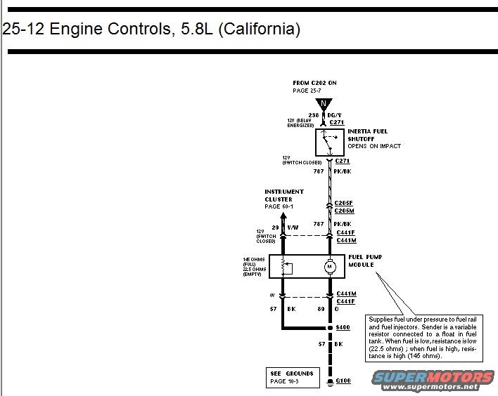
Ford 5.8L California Fuel Pump Module Wiring Diagram - Engine Controls 25-12
Reference · 1992-1996 BroncoAll 411 wiring diagrams



















Wiring diagram of 5.8L California engine controls showing inertia fuel shutoff switch and fuel pump module sender circuit with resistance values.
Part of 1992-1996 Ford Bronco Wiring Diagrams
This document is a page from a factory-style wiring diagram set, labeled "25-12 Engine Controls, 5.8L (California)". It shows the fuel pump circuit for the California-emissions 5.8L engine. Power comes from connector C202 (referenced on page 25-7) via circuit 238 (DG/Y wire) to connector C271 and the Inertia Fuel Shutoff switch, which opens on impact. From the shutoff, circuit 787 (PK/BK wire) carries 12V (switch closed) through connectors C205F/C205M and C441F/C441M to the Fuel Pump Module. The module contains the fuel pump motor and the fuel level sender, a variable resistor reading 22.5 ohms when empty and 145 ohms when full; the sender signal goes to the instrument cluster (page 60-1) on circuit 29 (Y/W wire). Ground paths leave the module on circuits 57 (BK) and 89 (O) through C441M/C441F, join at splice S400, and continue on circuit 57 BK to ground G100 (see grounds, page 10-3). A callout explains that the module supplies fuel under pressure to the fuel rail and injectors. The page gives circuit numbers, wire colors, connector IDs, voltage conditions, and resistance specs useful for diagnosing fuel pump or fuel gauge problems.
Is this accurate? Sign in to help verify it.
Frequently asked questions
- What wire color and circuit feeds the inertia fuel shutoff switch?
- Circuit 238, a DG/Y (dark green/yellow) wire coming from C202 (page 25-7), enters the inertia fuel shutoff at connector C271, with 12V present when the relay is energized.
- What circuit powers the fuel pump module after the inertia switch?
- Circuit 787, a PK/BK wire, carries 12V (switch closed) from C271 through connectors C205F/C205M and C441F/C441M to the fuel pump module.
- What are the fuel level sender resistance values?
- The sender reads 22.5 ohms when the tank is empty and 145 ohms when full; resistance is low when fuel is low and high when fuel is high.
- How is the fuel pump module grounded?
- Two grounds leave the module through C441M/C441F: circuit 57 (BK) and circuit 89 (O). They join at splice S400 and continue on circuit 57 BK to ground G100 (grounds shown on page 10-3).
- What wire carries the fuel level signal to the instrument cluster?
- Circuit 29, a Y/W wire, goes to the instrument cluster (referenced on page 60-1).






No comments yet.