Home/
Registry/
Ford/
Bronco/
1992-1996/
“Eddie Bauer”/
Photo
supermotors.net/registry/media/1157085
1994 Ford Bronco/F-Series 5.8L PCM Connector C185 Pinout - Wire Colors
Reference · 1992-1996 BroncoAll 15 fuse & relay charts


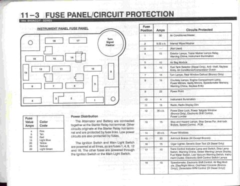
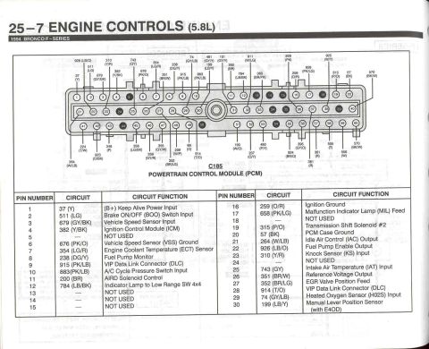

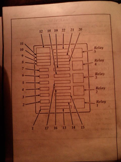
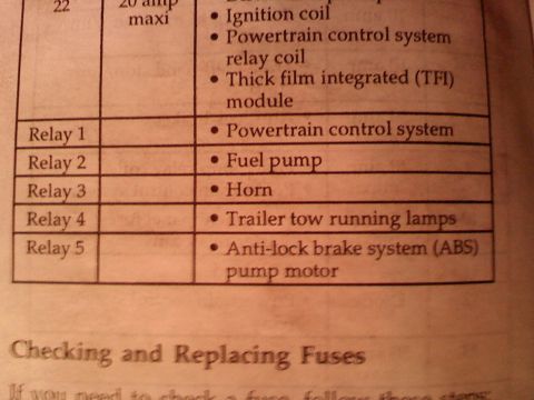










Powertrain Control Module C185 connector pinout chart listing each pin number, circuit and circuit function for the 5.8L engine controls.
Part of 1992-1996 Ford Bronco Fuse & Relay Charts
This document is page 25-7, "Engine Controls (5.8L)," from the 1994 Ford Bronco/F-Series electrical & vacuum troubleshooting manual (EVTM). It shows the pinout for connector C185, the 60-pin Powertrain Control Module (PCM) connector. A connector-face diagram numbers all 60 pins and calls out the circuit number and wire color for each populated pin (e.g., 37 Y, 926 LB/O, 354 LG/R, 570 BK/W). Below the diagram, a table lists pins 1-30 with their circuit number, wire color code, and circuit function. Functions covered include (B+) Keep Alive Power Input, Brake ON/OFF (BOO) Switch Input, Vehicle Speed Sensor Input/Ground, Ignition Control Module (ICM), Engine Coolant Temperature (ECT) Sensor, Fuel Pump Monitor and Fuel Pump Enable Output, VIP Data Link Connector (DLC), A/C Cycle Pressure Switch, AIRD Solenoid, 4x4 Low Range indicator lamp, Ignition Ground, MIL feed, Transmission Shift Solenoid #2, PCM Case Ground, Idle Air Control output, Knock Sensor input, IAT input, Reference Voltage Output, EGR Valve Position Feed, Heated Oxygen Sensor (HO2S) input, and Manual Lever Position Sensor (with E4OD). Several pins (5, 13, 14, 15, 18, 24) are marked NOT USED. A reader can identify PCM wires by pin number, circuit number, and color for diagnostics on 1994 5.8L Bronco/F-Series trucks.
Is this accurate? Sign in to help verify it.
Frequently asked questions
- What connector is shown on page 25-7 of the 1994 Bronco/F-Series EVTM?
- Connector C185, the 60-pin Powertrain Control Module (PCM) connector for the 5.8L engine controls.
- Which PCM pin is the fuel pump enable output on a 1994 5.8L Bronco?
- Pin 22, circuit 926 (LB/O: light blue/orange), is the Fuel Pump Enable Output. Pin 8, circuit 238 (DG/Y), is the Fuel Pump Monitor.
- Which PCM pins are not used on the 1994 5.8L C185 connector?
- Pins 5, 13, 14, 15, 18, and 24 are listed as NOT USED in the table shown.
- What wire color is the Engine Coolant Temperature (ECT) sensor at the PCM?
- Pin 7, circuit 354 (LG/R: light green/red), is the ECT Sensor circuit.
- Which pin carries the Malfunction Indicator Lamp (MIL) feed?
- Pin 17, circuit 658 (PK/LG: pink/light green), is the Malfunction Indicator Lamp (MIL) Feed.






No comments yet.