Home/
Registry/
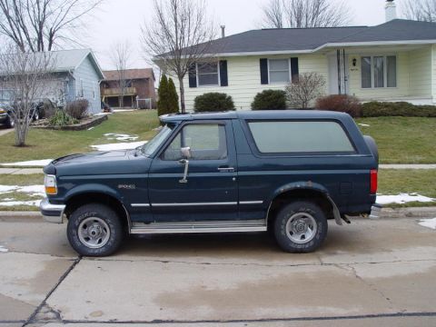
Ford/
Bronco/
1992-1996/
“badassbronco”/
Photo
supermotors.net/registry/media/155347
Ford 7.3L DI Turbo Diesel PCM Connector C1027 Pinout - Powerstroke Wiring Diagram

Powertrain control module connector C1027 pinout for a 7.3L DI turbo diesel, showing pin layout with wire colors and circuit functions.
Part of 1992-1996 Ford Bronco Wiring Diagrams
This document is a connector pinout reference for the C1027 (gray) 104-pin Powertrain Control Module (PCM) connector used with the 7.3L DI Turbo diesel (Powerstroke) engine, as labeled '7.3L DIESEL.' The diagram shows the physical connector face with pins numbered 1 through 104 arranged in four rows, with callout leaders identifying circuit numbers and wire color codes (e.g., 315 P/O, 658 PK/LG, 977 P/W, 570 BK/W). Circuits marked with an asterisk apply only to trucks equipped with the E4OD automatic transmission. Below the diagram, a three-column table lists pins 1-32 with their circuit numbers, wire colors, and functions, including Transmission Shift Solenoids #1 and #2, Check Engine Light, Brake Warning Indicator, Idle Validation Switch, Generic Scan Tool Inputs, 4x4 Low Input, Auxiliary Powertrain Control Input, Ground, Torque Converter Clutch Solenoid, Clutch Pedal Position Switch, Transmission Control Switch, Exhaust Back Pressure Sensor, and Brake Pressure Switch. Many pins are listed as NOT USED. A reader can use this page to identify which PCM pin and wire color corresponds to each engine/transmission control circuit for diagnostics or wiring repair. Note that this appears to be one page of a multi-page set (a companion scan exists in the same album), likely covering additional pins beyond 32.
Is this accurate? Sign in to help verify it.
Frequently asked questions
- What connector does this diagram cover?
- It covers C1027, the gray Powertrain Control Module (PCM) connector for the 7.3L DI Turbo diesel engine.
- Which PCM pin is ground on the 7.3L diesel C1027 connector?
- Pin 25, circuit 57 with a black (BK) wire, is listed as Ground.
- What do the asterisks (*) next to some circuits mean?
- The note states '* WITH E4OD TRANSMISSION', asterisked circuits (e.g., Transmission Shift Solenoids #1 and #2, Torque Converter Clutch Solenoid) apply only with the E4OD transmission.
- Which pins control the transmission shift solenoids?
- Pin 1 (circuit 315, P/O) is Transmission Shift Solenoid #2 and pin 27 (circuit 237, O/Y) is Transmission Shift Solenoid #1, both used with the E4OD transmission.
- What wire goes to the Check Engine Light?
- Pin 2, circuit 658 with a pink/light green (PK/LG) wire, is the Check Engine Light circuit.
Comments
More from this build






No comments yet.