Home/
Registry/
Ford/
Bronco/
1992-1996/
“badassbronco”/
Photo
supermotors.net/registry/media/180094
2.0L VIN C PCM Connector C4 Pinout - 30-Pin Wire Colors & Functions

Reference · 1992-1996 BroncoAll 411 wiring diagrams
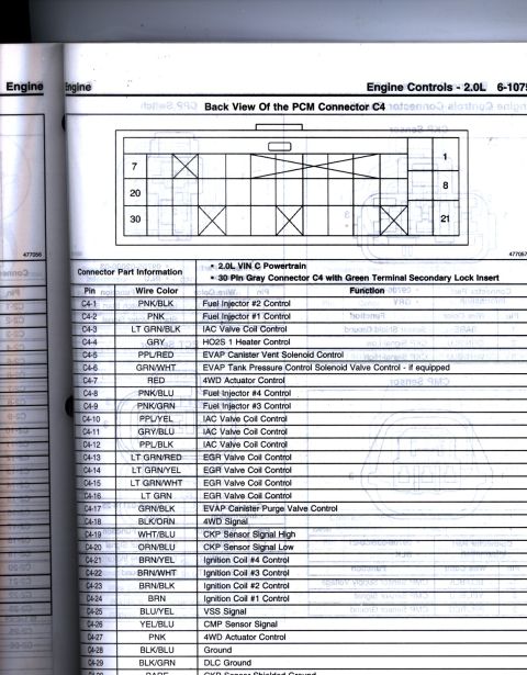
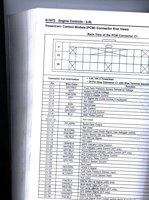
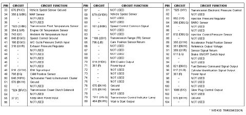
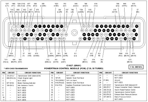
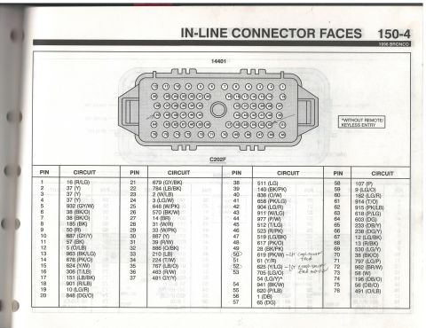
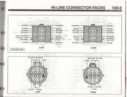
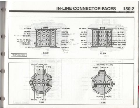
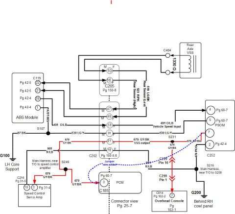
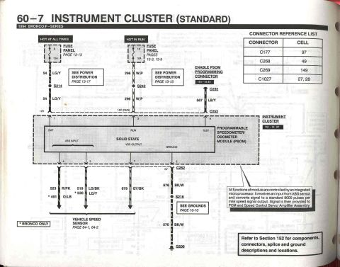
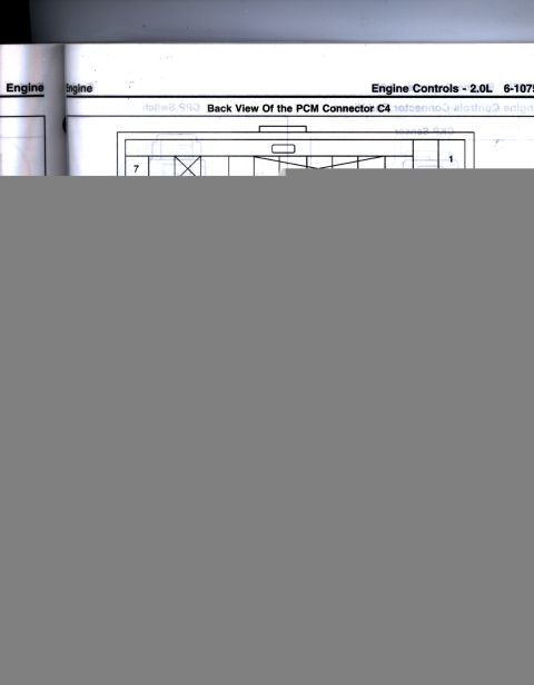




Wiring chart showing the 2.0L PCM connector C4 back view with a pin-by-pin wire-color and function table.
Part of 1992-1996 Ford Bronco Wiring Diagrams
This scanned service-manual page (page header 'Engine Controls - 2.0L, 6-107x') shows the back view of Powertrain Control Module (PCM) connector C4 for a 2.0L VIN C powertrain. The connector is described as a 30-pin gray connector C4 with a green terminal secondary lock insert; a diagram illustrates the connector cavity layout with pins 1, 7, 8, 20, 21, and 30 labeled for orientation (illustration numbers 477056 and 477057). Below the diagram is a complete pinout table listing pin numbers C4-1 through C4-30 with their wire colors and circuit functions. Circuits include fuel injector controls #1-#4, four IAC valve coil control circuits, HO2S 1 heater control, EVAP canister vent solenoid, EVAP tank pressure control solenoid (if equipped), EVAP canister purge valve, four EGR valve coil control circuits, 4WD actuator control and 4WD signal, CKP sensor signal high/low, ignition coil #1-#4 controls, VSS signal, CMP sensor signal, ground, DLC ground, and CKP sensor shielded ground (bare wire). A reader can use this page to identify PCM wire colors and functions at connector C4 for diagnostics on the 2.0L engine's fuel, ignition, emissions, and 4WD circuits.
Is this accurate? Sign in to help verify it.
Frequently asked questions
- What connector does this diagram cover?
- The back view of PCM connector C4, a 30-pin gray connector with a green terminal secondary lock insert, for the 2.0L VIN C powertrain.
- Which pins control the fuel injectors?
- C4-1 (PNK/BLK) Fuel Injector #2, C4-2 (PNK) Fuel Injector #1, C4-8 (PNK/BLU) Fuel Injector #4, and C4-9 (PNK/GRN) Fuel Injector #3.
- What wire colors are the CKP sensor signal circuits?
- C4-19 WHT/BLU is CKP Sensor Signal High, C4-20 ORN/BLU is CKP Sensor Signal Low, and C4-30 is a BARE wire for the CKP Sensor Shielded Ground.
- Which pins are the ignition coil controls?
- C4-21 (BRN/YEL) Coil #4, C4-22 (BRN/WHT) Coil #3, C4-23 (BRN/BLK) Coil #2, and C4-24 (BRN) Coil #1.
- What is the VSS signal wire color at the PCM?
- Pin C4-25, wire color BLU/YEL, is the VSS Signal.






No comments yet.