Home/
Registry/
Ford/
Bronco/
1992-1996/
“badassbronco”/
Photo
supermotors.net/registry/media/180091
2.0L VIN C PCM Connector C2 Pinout - 26-Pin Wire Colors & Functions (6-1073)
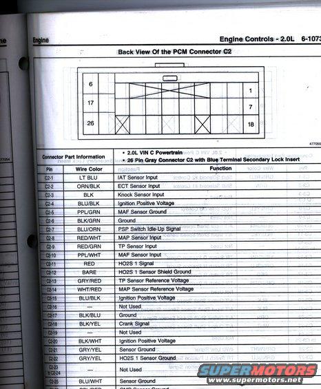
Wiring chart showing the 2.0L PCM connector C2 back view with a pin-by-pin wire-color and function table.
Part of 1992-1996 Ford Bronco Wiring Diagrams
This scanned service-manual page (page 6-1073, 'Engine Controls - 2.0L') shows the back view of PCM Connector C2 for a 2.0L VIN C powertrain. The connector is described as a 26-pin gray connector C2 with a blue terminal secondary lock insert. A diagram at the top illustrates the connector's rear cavity layout with pin position references (1, 6, 7, 17, 18, 26), followed by a complete pinout table listing each pin (C2-1 through C2-26), its wire color, and its circuit function. Functions covered include the IAT, ECT, knock, MAP, TP, and MAF sensor inputs and grounds; HO2S 1 signal, shield ground, and sensor ground; ignition positive voltage feeds (C2-4, C2-15, C2-20); grounds; the PSP switch idle-up signal; the crank signal; and sensor grounds, ending with what appears to be a CMP sensor ground at C2-26. Several pins (C2-16, C2-19, C2-23 to C2-24) are marked Not Used. A reader can use this page to identify wire colors and circuit functions at each PCM C2 terminal for diagnostics on a 2.0L VIN C engine. Reference figure number 477055 appears below the diagram. Note: this GM-format 2.0L document does not match the uploader's claimed 1992 Ford Bronco.
Is this accurate? Sign in to help verify it.
Frequently asked questions
- What are the pin functions of PCM connector C2 on the 2.0L VIN C engine?
- The table lists all 26 pins, e.g., C2-1 (LT BLU) IAT Sensor Input, C2-2 (ORN/BLK) ECT Sensor Input, C2-3 (BLK) Knock Sensor Input, C2-8 (RED/WHT) MAP Sensor Input, C2-9 (RED/GRN) TP Sensor Input, C2-10 (PPL/WHT) MAF Sensor Input, C2-11 (RED) HO2S 1 Signal, and C2-18 (BLK/YEL) Crank Signal.
- What type of connector is PCM connector C2?
- It is a 26-pin gray connector C2 with a blue terminal secondary lock insert, used on the 2.0L VIN C powertrain.
- Which C2 pins carry ignition positive voltage?
- C2-4 (BLU/BLK), C2-15 (BLU/BLK), and C2-20 (BLK/WHT) are all listed as Ignition Positive Voltage.
- Which pins on connector C2 are not used?
- C2-16, C2-19, and C2-23 through C2-24 are marked Not Used.
- What wire color is the HO2S 1 signal and its shield ground?
- The HO2S 1 signal is a RED wire at C2-11, and the HO2S 1 sensor shield ground is a BARE wire at C2-12; C2-22 (GRY/YEL) is the HO2S 1 sensor ground.
Comments
More from this build






No comments yet.