Home/
Registry/
Ford/
Bronco/
1992-1996/
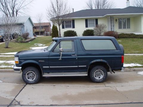
“badassbronco”/
Photo
supermotors.net/registry/media/180090
2.0L VIN C PCM Connector C1 Pinout - 35-Pin Wire Colors & Functions
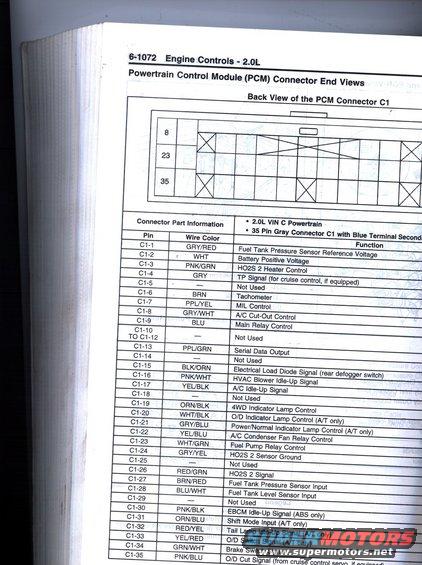
Service-manual page 6-1072: back view of the PCM gray connector C1 plus a pin-by-pin wire-color/function table (fuel tank pressure, MIL control, tach, fuel pump relay, HO2S, 4WD lamp).
Part of 1992-1996 Ford Bronco Wiring Diagrams
This scanned service manual page (page 6-1072, 'Engine Controls - 2.0L') presents Powertrain Control Module (PCM) connector end views for a 2.0L VIN C powertrain. It includes a diagram labeled 'Back View of the PCM Connector C1' showing a 35-pin gray connector (C1) with blue terminal secondary lock, with pin position rows marked 8, 23, and 35. Below the diagram is a complete pinout table listing each of the 35 pins (C1-1 through C1-35), the corresponding wire color, and the circuit function. Notable circuits include Battery Positive Voltage (C1-2, WHT), HO2S 2 Heater Control (C1-3, PNK/GRN), Tachometer (C1-6, BRN), MIL Control (C1-7, PPL/YEL), Main Relay Control (C1-9, BLU), Serial Data Output (C1-13, PPL/GRN), 4WD Indicator Lamp Control (C1-19, ORN/BLK), Fuel Pump Relay Control (C1-23, WHT/GRN), HO2S 2 Signal (C1-26, RED/GRN), fuel tank pressure and level sensor inputs (C1-27, C1-28), and Brake Switch Signal (C1-34, GRN/WHT). Several pins (C1-5, C1-10 to C1-12, C1-14, C1-18, C1-25, C1-29) are marked Not Used. This page is useful for diagnosing PCM-related wiring on a 2.0L VIN C engine, though it does not match a 1992 Ford Bronco.
Is this accurate? Sign in to help verify it.
Frequently asked questions
- What connector does this page cover?
- The 35-pin gray PCM connector C1 with blue terminal secondary lock for a 2.0L VIN C powertrain, shown from the back view.
- Which pin on connector C1 controls the fuel pump relay?
- Pin C1-23, wire color WHT/GRN, is Fuel Pump Relay Control.
- Which PCM C1 pins are not used?
- C1-5, C1-10 through C1-12, C1-14, C1-18, C1-25, and C1-29 are listed as Not Used.
- What wire color is the tachometer signal at the PCM?
- The tachometer signal is on pin C1-6 with a BRN (brown) wire.
- Where is the serial data output on this PCM connector?
- Serial Data Output is on pin C1-13, wire color PPL/GRN.
Comments
More from this build






No comments yet.