Home/
Registry/
Ford/
Bronco/
1992-1996/
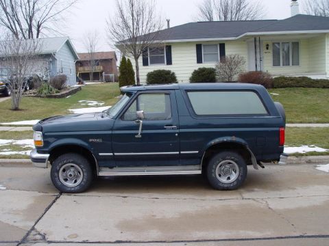
“badassbronco”/
Photo
supermotors.net/registry/media/176257
H9411 Exploded Valve Assembly Parts Diagram: Callouts 1-16 (Relief Valve)

Line-art exploded parts breakdown of a pump assembly with numbered callouts for housings, springs, washers and fittings.
Part of 1992-1996 Ford Bronco Exploded Parts Diagrams
This document is an exploded parts diagram (illustration ID H9411) showing a valve assembly, most likely a hydraulic pressure relief or control valve, disassembled along its axis. The drawing contains numbered callouts 1 through 16 pointing to individual components but includes no accompanying parts legend, part numbers, torque values, or descriptive text. Visible components include mounting bolts and washers (items 1 and 2, shown at both top and bottom), two flanged end caps or housings (item 3), O-rings or gaskets (item 4), a small plug or fitting (item 5), the central valve body (item 6), a large spring (item 7), washers or spring seats (item 8, shown twice), a smaller inner spring (item 9), a poppet or valve stem (item 10), small sealing rings and balls (items 11, 12, 16), and a side-mounted screw with washer (items 13, 14) grouped under callout 15. A reader can learn the assembly order and orientation of these components for disassembly and reassembly, but must consult a separate parts list keyed to figure H9411 for part numbers and names. The only text in the image is the figure identifier 'H9411' in the lower left corner.
Is this accurate? Sign in to help verify it.
Frequently asked questions
- What figure or illustration number is this diagram?
- The only identifier visible in the image is 'H9411', printed in the lower left corner.
- How many numbered parts are shown in this exploded diagram?
- Callouts numbered 1 through 16 are shown; numbers 1, 2, 3, 4, and 8 each appear twice on duplicate components.
- Does this diagram include a parts list or part numbers?
- No. The diagram contains only numbered callouts and the figure ID H9411; there is no legend, parts list, part numbers, or torque values in the image.
- What kind of assembly does the diagram appear to depict?
- It shows a valve-type assembly: a central body (item 6) with end caps (3), gaskets/O-rings (4), springs (7 and 9), washers/seats (8), a poppet/stem (10), and mounting bolts (1) with washers (2).
Comments
More from this build





No comments yet.